
Page 348 - Fundamentals of Magnetic Thermonuclear Reactor Design
P. 348
Power Supply Systems Chapter | 11 325
TABLE 11.1 Key Parameters of Power Supply Systems Used for Resistive
Toroidal Field Coils
T-10 JT-60 JET
Parameters (Russia) D-III (USA) TFTR (USA) (Japan) (EU)
Energy stored in 126 244 1370 2850 1450
magnetic field (MJ)
Energy loss in coils 400 236 2400 9300 4050
(MJ)
Max power of PS 180 150 670 420 422
source (MVA)
Max active power 140 126 480 360 360
(MW)
Max reactive power 130 80 530 320 260
(MWAr)
Max current (kA) 20 127 74 52 67
Max voltage of 9 1.2 9.1 8 7.2
power supply (kV)
Plasma discharge 6.2 9 17 56 32
duration (s)
Operating cycle 30 5 5 10 15
duration (min)
AC power supply Network Synchronous Synchronous Grid + Grid
generator generator synchronous
generator
JET, Joint european torus.
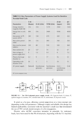
FIGURE 11.1 The TM-4 tokamak power supply circuit. CB, Capacitor-bank; D, diode; IT,
ignitron trigger; R, rectifier; TFC, toroidal field coil; Тr, transformer; TS, thyristor switch.
It acted as a by-pass, allowing current ramp-down at a time-constant rate
depending on the coil parameters. Although simple and reliable, this design has
limited applicability associated with the machine’s small size that determined
the use of TFC switch stored energies of a few megajoules.
Electric valve AC/DC converters intended, in principle, for stationary
loads, have been used for the PS of tokamaks, beginning with the T-3 machine.