
Page 353 - Fundamentals of Magnetic Thermonuclear Reactor Design
P. 353
330 Fundamentals of Magnetic Thermonuclear Reactor Design
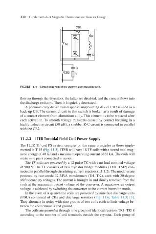
FIGURE 11.4 Circuit diagram of the current commutating unit.
flowing through the thyristors, the latter are disabled, and the current flows into
the discharge resistors. Then, it is quickly decreased.
A pneumatically driven fast-response single-acting device CB2 is used as a
back-up CB. The current circuit in this switch is broken as a result of damage
of a contact element from aluminium alloy. This element is to be replaced after
each activation. To smooth voltage transients caused by contact breaking in a
highly inductive circuit (50 µH), a snubber R-C circuit is connected in parallel
with the CB2.
11.2.3 ITER Toroidal Field Coil Power Supply
The ITER TF coil PS system operates on the same principles as those imple-
mented in T-15 (Fig. 11.5). ITER will have 18 TF coils with a stored total mag-
netic energy of 40 GJ and a maximum operating current of 68 kA. The coils will
make nine pairs connected in series.
The TF coils are powered by a 12-pulse TC with a no-load nominal voltage
of 900 V. The TC consists of two thyristor bridge modules (TM1, TM2) con-
nected in parallel through circulating-current reactors (L1, L2). The modules are
powered by two-anode 32 MVA transformers (Tr1, Tr2), each with 30-degree
shift secondary voltages. The current is brought in and slowly removed from the
coils at the maximum output voltage of the converter. A negative-sign output
voltage is achieved by switching the converter to the current inversion mode.
In the event of a quench the coils are protected by nine fast discharge units
(FDU) composed of CBs and discharge resistors (Fig. 11.6; Table 11.3) [3].
They alternate in series with nine groups of two coils each to limit voltage be-
tween the coil terminals and ground.
The coils are grounded through nine groups of identical resistors TR1–TR18
according to the number of coil terminals outside the cryostat. Each group of