
Page 355 - Fundamentals of Magnetic Thermonuclear Reactor Design
P. 355
332 Fundamentals of Magnetic Thermonuclear Reactor Design
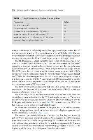
TABLE 11.3 Key Parameters of the Fast Discharge Unit
Parameters Values
Nominal current (kA) 68
Energy dissipated in resistors (GJ) 35
Equivalent time constant of energy discharge (s) 11
Maximum voltage (between coil terminals) (kV) 8
Maximum voltage to ground at normal operation (kV) 4
Insulation class/test voltage (50 Hz) (kV) 12/28
nominal current and is actuated by an external signal for coil protection. The PB
is a back-up single-acting PB provided in case of an MCB failure [4]. The pro-
tective make switch (PMS) is switched on immediately before energy discharge,
shunting the output of the TC and confining the current discharge circuit.
The MCB consists of a high-current by-pass switch (BPS) connected in par-
allel to a vacuum circuit breaker (VCB). The BPS is intended for continuous
operation at nominal current and switching of current into the low-inductance
circuit made by VCB closed contacts, when a signal for fast discharge arrives.
The VCB opens the coil circuit with the help of a counterpulse circuit (CPC):
the thyristor switch (TS) is closed and the capacitor bank (C) discharges through
the VCB in the direction opposite to the coil current, switching the current to
a fast discharge resistor (FDR). A snubber circuit (SC) is connected in parallel
to the switches to smooth potential overvoltage on the coil and to reduce the
reverse voltage on the CPC capacitors.
The PMS switch employs the same BPS and VCB turned on for closure in
the reverse order. Besides, an extra protective make switch (EPMS) is provided
in case of a failure of one of them.
The BPS and VCB are based on commercial switches that have been sub-
stantially upgraded and adapted to the ITER technical requirements. The ground
insulation was reinforced, the interpole spaces of BPS were enlarged, and the
BPS speed and lifetime were increased [5,6]. The back-up switches, EPMS, are
fast-response single-acting pyro-activated devices.
To minimise inductance, the FDRs are designed as a set of unified elements
made of a zigzag-folded tape from carbon steel with a high-temperature coef-
ficient of electrical resistance (Fig. 11.7).
The mass of the resistive elements is selected so that they are heated by
200–250°C at maximum energy absorption. An increase in the FDR resistance
with temperature accelerates energy discharge as compared to alternative cir-
cuits with constant resistance, when the current drops exponentially. One can
shorten the current discharge duration or reduce voltage applied to the coil at the
beginning of discharge, depending on technical requirements.