
Page 360 - Fundamentals of Magnetic Thermonuclear Reactor Design
P. 360
Power Supply Systems Chapter | 11 337
opposite-polarity converters connected to an AC network. Self-charging current or
voltage inverters are employed, where it is necessary to increase operation speed.
11.3.3 ITER Poloidal Field Coil Power Supply
The poloidal magnetic fields of the ITER tokamak are generated by electric
currents flowing in six CS coils (three upper modules, CSU1–CS5U3, and three
lower modules CSL1–CSL3) and in six PF coils, PF1–PF6. Their PS systems
perform three functions, namely, power delivery according to the operating
cycle scenario, coil protection in the event of quench and grounding.
The coils are conventionally divided into two groups. The first group in-
cludes the PF1 and PF6 coils, whose function is to generate, together with
the CS, the magnetic field for plasma positioning and shaping, as well as to
maintain its equilibrium state. With this aim in view, currents in these coils are
relatively slowly regulated.
The second group includes the PF2–PF5 coils intended for the plasma verti-
cal stabilisation (VS) through their current feedback control. The coils of the
first group have individual PS systems, except for the upper and lower modules
of the CS1 coil connected in series and powered by one TC. The PF2–PF5 coils
have a common PS system.
Power Supply Systems of CS, PF1 and PF6 Coils. The pattern of current
variation in the CS1–CS6 coils, as well as in the nearby PF1 and PF6 coils, is
typical of large tokamaks. Similar requirements are imposed upon the power
supplies of these coils, namely, high voltage and augmented power (from 300
to 380 MW per coil) at breakdown and initial development of plasma discharge
up to 15 s, and a relatively limited power (to 50 MW) during the main portion
of the pulse up to 900 s in length.
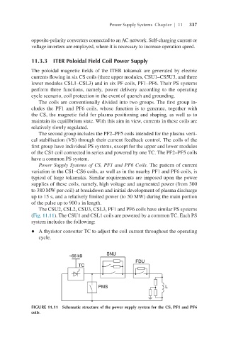
The CSU2, CSL2, CSU3, CSL3, PF1 and PF6 coils have similar PS systems
(Fig. 11.11). The CSU1 and CSL1 coils are powered by a common TC. Each PS
system includes the following:
l A thyristor converter TC to adjust the coil current throughout the operating
cycle.
FIGURE 11.11 Schematic structure of the power supply system for the CS, PF1 and PF6
coils.