
Page 361 - Fundamentals of Magnetic Thermonuclear Reactor Design
P. 361
338 Fundamentals of Magnetic Thermonuclear Reactor Design
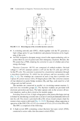
FIGURE 11.12 Block diagram of the reversible thyristor converter.
l A switching network unit (SNU), which together with the TC generates a
high-voltage pulse for gas breakdown and plasma formation at the begin-
ning of the cycle.
l An FDU designed to dissipate energy stored in the superconducting coils to
protect them in case of quench and other emergency situations. Besides, the
PS system has a PMS, shunting the converter in case of a failure and at fast
energy discharge.
Thyristor Converter. All TCs are composed of unified modules. On-load
voltage is 1.05 kV; nominal current is ±45 kA for the CS coils and ±55 kA
for the PF coils. The converter is powered by a transformer substation through
a step-down transformer, Tr, which has two primary and two secondary coils
(Fig. 11.12). The windings are connected in such a way that it provides two
3-phase AC power sources with a 30-degree phase shift. The converter consists
of four identical six-pulse bridge modules (M and M ), each rated for a full
F
B
voltage and one-half current.
The modules are connected in parallel via circulating-current reactors, L,
and form two reversible groups [8]. The thyristor modules are provided with
electronic protection and fuses. The latter operate only in the severest off-nor-
mal situations, such as short-circuit at the module output.
Switching Network Unit. A high-voltage pulse at the plasma discharge start-up
is formed by introducing a resistor into a circuit of current preliminarily delivered
into the coil. The circuit is provided with a CB, whose closed contacts shunt the
resistor when current is delivered (Fig. 11.13) [9]. Maximum voltage appearing at
operation of the SNU CB is 8.5 kV at a current of 45 kA (35 kA in the PF6 coil).
The SNU is comprised of the following:
l A high-current BPS containing contact-thyristor fast-open switch (FOS),
connected in series with a fast disconnect switch (FDS);