
Page 362 - Fundamentals of Magnetic Thermonuclear Reactor Design
P. 362
Power Supply Systems Chapter | 11 339
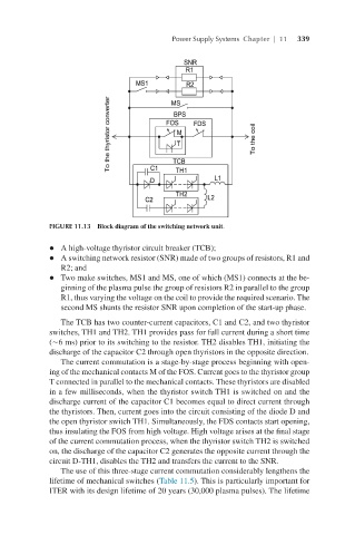
FIGURE 11.13 Block diagram of the switching network unit.
l A high-voltage thyristor circuit breaker (TCB);
l A switching network resistor (SNR) made of two groups of resistors, R1 and
R2; and
l Two make switches, MS1 and MS, one of which (MS1) connects at the be-
ginning of the plasma pulse the group of resistors R2 in parallel to the group
R1, thus varying the voltage on the coil to provide the required scenario. The
second MS shunts the resistor SNR upon completion of the start-up phase.
The TCB has two counter-current capacitors, C1 and C2, and two thyristor
switches, TH1 and TH2. TH1 provides pass for full current during a short time
(∼6 ms) prior to its switching to the resistor. TH2 disables TH1, initiating the
discharge of the capacitor C2 through open thyristors in the opposite direction.
The current commutation is a stage-by-stage process beginning with open-
ing of the mechanical contacts M of the FOS. Current goes to the thyristor group
T connected in parallel to the mechanical contacts. These thyristors are disabled
in a few milliseconds, when the thyristor switch TH1 is switched on and the
discharge current of the capacitor C1 becomes equal to direct current through
the thyristors. Then, current goes into the circuit consisting of the diode D and
the open thyristor switch TH1. Simultaneously, the FDS contacts start opening,
thus insulating the FOS from high voltage. High voltage arises at the final stage
of the current commutation process, when the thyristor switch TH2 is switched
on, the discharge of the capacitor C2 generates the opposite current through the
circuit D-TH1, disables the TH2 and transfers the current to the SNR.
The use of this three-stage current commutation considerably lengthens the
lifetime of mechanical switches (Table 11.5). This is particularly important for
ITER with its design lifetime of 20 years (30,000 plasma pulses). The lifetime