
Page 359 - Fundamentals of Magnetic Thermonuclear Reactor Design
P. 359
336 Fundamentals of Magnetic Thermonuclear Reactor Design
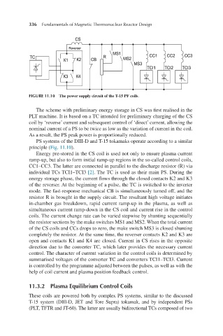
FIGURE 11.10 The power supply circuit of the T-15 PF coils.
The scheme with preliminary energy storage in CS was first realised in the
PLT machine. It is based on a TC intended for preliminary charging of the CS
coil by ‘reverse’ current and subsequent control of ‘direct’ current, allowing the
nominal current of a PS to be twice as low as the variation of current in the coil.
As a result, the PS peak power is proportionally reduced.
PS systems of the DIII-D and T-15 tokamaks operate according to a similar
principle (Fig. 11.10).
Energy pre-stored in the CS coil is used not only to ensure plasma current
ramp-up, but also to form initial ramp-up regions in the so-called control coils,
CC1–CC3. The latter are connected in parallel to the discharge resistor (R) via
individual TCs TCI1–TCI3 [2]. The TC is used as their main PS. During the
energy storage phase, the current flows through the closed contacts K2 and K3
of the reverser. At the beginning of a pulse, the TC is switched to the inverter
mode. The fast-response mechanical CB is simultaneously turned off, and the
resistor R is brought in the supply circuit. The resultant high voltage initiates
in-chamber gas breakdown, rapid current ramp-up in the plasma, as well as
simultaneous current ramp-down in the CS coil and current rise in the control
coils. The current change rate can be varied stepwise by shunting sequentially
the resistor sections by the make switches MS1 and MS2. When the total current
of the CS coils and CCs drops to zero, the make switch MS3 is closed shunting
completely the resistor. At the same time, the reverser contacts K2 and K3 are
open and contacts K1 and K4 are closed. Current in CS rises in the opposite
direction due to the converter TC, which later provides the necessary current
control. The character of current variation in the control coils is determined by
summarised voltages of the converter TC and converters TCI1–TCI3. Current
is controlled by the programme adjusted between the pulses, as well as with the
help of coil current and plasma position feedback control.
11.3.2 Plasma Equilibrium Control Coils
These coils are powered both by complex PS systems, similar to the discussed
T-15 system (DIII-D, JET and Tore Supra) tokamak, and by independent PSs
(PLT, TFTR and JT-60). The latter are usually bidirectional TCs composed of two