
Page 354 - Fundamentals of Magnetic Thermonuclear Reactor Design
P. 354
Power Supply Systems Chapter | 11 331
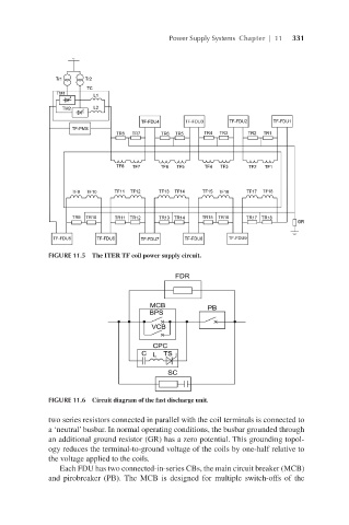
FIGURE 11.5 The ITER TF coil power supply circuit.
FIGURE 11.6 Circuit diagram of the fast discharge unit.
two series resistors connected in parallel with the coil terminals is connected to
a ‘neutral’ busbar. In normal operating conditions, the busbar grounded through
an additional ground resistor (GR) has a zero potential. This grounding topol-
ogy reduces the terminal-to-ground voltage of the coils by one-half relative to
the voltage applied to the coils.
Each FDU has two connected-in-series CBs, the main circuit breaker (MCB)
and pirobreaker (PB). The MCB is designed for multiple switch-offs of the