
Page 357 - Fundamentals of Magnetic Thermonuclear Reactor Design
P. 357
334 Fundamentals of Magnetic Thermonuclear Reactor Design
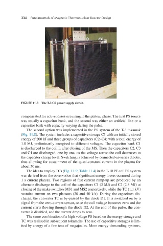
FIGURE 11.8 The T-3 CS power supply circuit.
compensated for active losses occurring in the plateau phase. The first PS source
was usually a capacitor bank, and the second was either an artificial line or a
capacitor bank with capacity varying during the pulse.
The second option was implemented in the PS system of the T-3 tokamak
(Fig. 11.8). The system includes a capacitive storage C1 with an initially stored
energy of 200 kJ and three groups of capacitors (C2–C4) with a total energy of
1.8 MJ, preliminarily energised to different voltages. The capacitor bank C1
is discharged to the coil L after closing of the MS. Then the capacitors C2, C3
and C4 are discharged, one by one, as the voltage across the coil decreases to
the capacitor charge level. Switching is achieved by connected-in-series diodes,
thus allowing for sustainment of the quasi-constant current in the plasma for
about 50 ms.
The idea to employ TCs (Fig. 11.9; Table 11.4) in the T-10 PF coil PS system
was derived from the observation that significant energy losses occurred during
1 s current plateau. Two regions of fast current ramp-up are produced by an
alternate discharge to the coil of the capacitors C1 (3 MJ) and C2 (2.5 MJ) at
closing of the make switches MS1 and MS2 respectively, while the TC (1.1 kV)
sustains current on two plateaus (20 and 40 kA). During the capacitors dis-
charge, the converter TC is by-passed by the diode D1. It is switched on by a
signal from the zero-current sensor, once the coil voltage becomes zero and the
current starts flowing through the diode D2. At the end of the pulse, the con-
verter is disabled, and the current drops to zero.
The same combination of a high-voltage PS based on the energy storage and
TC was realised in subsequent tokamaks. The use of capacitive storages is lim-
ited by energy of a few tens of megajoules. More energy-demanding systems,