
Page 358 - Fundamentals of Magnetic Thermonuclear Reactor Design
P. 358
Power Supply Systems Chapter | 11 335
such as the Joint European Torus (JET) CS, require inductive storage. One in-
teresting solution is to use the coil itself as an inductive storage [7]. This can
be realised by charging the coil, before the start of the operating pulse, by a
current with a polarity opposite to that of the ‘plateau’ current, and then by
introducing an active resistance into the circuit. The energy stored in the coil
magnet field dissipating in the resistor will help to generate power needed to
initiate the plasma current. This solution has an additional advantage of allow-
ing practically a two-fold change in the CS magnetic flux without a special coil
for pre-demagnetisation.
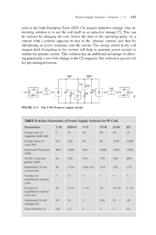
FIGURE 11.9 The T-10 CS power supply circuit.
TABLE 11.4 Key Parameters of Power Supply Systems for PF Coils
Parameters T-10 DIII-D T-15 TFTR JT-60 JET
Energy store in 5 32 30 85 60 25
magnetic field (MJ)
Energy losses in 9.6 230 10 65 1190 1200
coils (MJ)
Maximum PS power 400 3400 650 3600 2300 2500
(MW)
AC/DC converter 66 220 120 720 500 400
power (MW)
Maximum CS coil 40 ±150 +80/−40 ±24 ±92 ±70
current (kA)
Number of 1 12 3 1 4 3
equilibrium control
coils
Current of 20 5–20 7–18 24 22–94 5–20
equilibrium control
coils (kA)
Maximum CS coil 10 16 5 150 25 40
voltage (kV)
Pulse duration (s) 0.8 1.1 5 3 5 10