
Page 363 - Fundamentals of Magnetic Thermonuclear Reactor Design
P. 363
340 Fundamentals of Magnetic Thermonuclear Reactor Design
is extended by switching the current from the mechanical contacts M to the
thyristors T at a very low voltage (<20 V) making the arcing impossible. This
is facilitated by arranging the thyristors symmetrically around the coaxial me-
chanical contacts and in immediate proximity thereto. This topology decreases
the inductance of the FOS switching circuit to less than 0.2 µH.
In addition, there is no need for a series connection of several commercial
thyristors, as the operating voltage at the next commutation stage does not ex-
ceed 1 kV. Then, the FOS is completely insulated from high voltage by the FDS.
The major advantage of such switches is their high speed of operation.
Discharge resistors are composed of unified modules connected in parallel
by busbars. They make two groups, R1 and R2 (Fig. 11.15). The number of
parallel resistors in each group depends on the discharge scenario. The resistors
are made from a zigzag-shaped tape of stainless steel with a low-temperature
coefficient to avoid initial resistance variations from pulse to pulse.
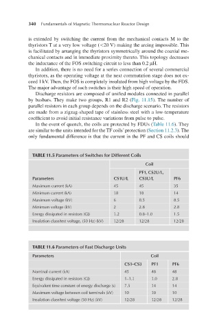
In the event of quench, the coils are protected by FDUs (Table 11.6). They
are similar to the units intended for the TF coils’ protection (Section 11.2.3). The
only fundamental difference is that the current in the PF and CS coils should
TABLE 11.5 Parameters of Switches for Different Coils
Coil
PF1, CS2U/L,
Parameters CS1U/L CS3U/L PF6
Maximum current (kA) 45 45 35
Minimum current (kA) 18 18 14
Maximum voltage (kV) 6 8.5 8.5
Minimum voltage (kV) 2 2.8 2.8
Energy dissipated in resistors (GJ) 1.2 0.8–1.0 1.5
Insulation class/test voltage, (50 Hz) (kV) 12/28 12/28 12/28
TABLE 11.6 Parameters of Fast Discharge Units
Parameters Coil
CS1–CS3 PF1 PF6
Nominal current (kA) 45 48 48
Energy dissipated in resistors (GJ) 1–1.1 1.0 2.8
Equivalent time constant of energy discharge (s) 7.5 14 14
Maximum voltage between coil terminals (kV) 10 10 10
Insulation class/test voltage (50 Hz) (kV) 12/28 12/28 12/28