
Page 365 - Fundamentals of Magnetic Thermonuclear Reactor Design
P. 365
342 Fundamentals of Magnetic Thermonuclear Reactor Design
l To stabilise the plasma, the PS system should provide an increased current
variation rate and, hence, an increased voltage of power supply sources;
l The quasisymmetrical current distribution in the upper (PF2 and PF3) and
lower (PF4 and PF5) coils allows the use of a common PS VS with a rela-
tively high output voltage and current not exceeding 50% of current in each
of the coils (55 kA). The current in each coil is controlled by two TCs con-
nected in series: one common converter for plasma VS and an individual
for each coil circuit MC. To this end, the coils arranged symmetrically rela-
tive to the reactor’s horizontal axis should be connected by the anti-parallel
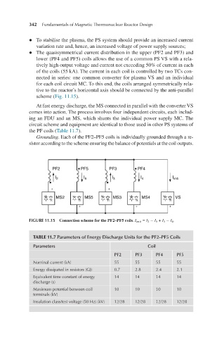
scheme (Fig. 11.15).
At fast energy discharge, the MS connected in parallel with the converter VS
comes into action. The process involves four independent circuits, each includ-
ing an FDU and an MS, which shunts the individual power supply MC. The
circuit scheme and equipment are identical to those used in other PS systems of
the PF coils (Table 11.7).
Grounding. Each of the PF2–PF5 coils is individually grounded through a re-
sistor according to the scheme ensuring the balance of potentials at the coil outputs.
FIGURE 11.15 Connection scheme for the PF2–PF5 coils. I im b = I 2 − I 5 + I 3 − I 4 .
TABLE 11.7 Parameters of Energy Discharge Units for the PF2–PF5 Coils
Parameters Coil
PF2 PF3 PF4 PF5
Nominal current (kA) 55 55 55 55
Energy dissipated in resistors (GJ) 0.7 2.8 2.4 2.1
Equivalent time constant of energy 14 14 14 14
discharge (s)
Maximum potential between coil 10 10 10 10
terminals (kV)
Insulation class/test voltage (50 Hz) (kV) 12/28 12/28 12/28 12/28