
Page 364 - Fundamentals of Magnetic Thermonuclear Reactor Design
P. 364
Power Supply Systems Chapter | 11 341
change direction. Therefore, the thyristor switches of the counterpulse capacitor
circuit are made by the bridge inverter circuit, so that the respective bridge arms
are switched on depending on the current direction.
Once a command for fast discharge arrives, the TC is switched into the in-
vertor mode and is shunted by the PMS. The latter is composed of two connect-
ed-in-parallel switches: a multiple-acting MS similar to that used in the current
commutation unit, and a back-up single-acting switch.
Grounding. The PF coils use the same grounding scheme as the TF coils.
Two series resistors are connected in parallel with each coil. Their common
point is grounded through a high-ohmic (1 kΩ) additional resistor. This makes
the coil terminals balanced relative to ground.
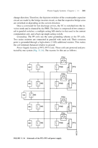
Power Supply Systems of PF2–PF5 Coils. These coils are powered and pro-
tected by one system (Fig. 11.14). The reasons for this are as follows:
FIGURE 11.14 Schematic of the PF2–PF5 coil power supply.