
Page 352 - Fundamentals of Magnetic Thermonuclear Reactor Design
P. 352
Power Supply Systems Chapter | 11 329
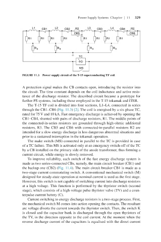
FIGURE 11.3 Power supply circuit of the T-15 superconducting TF coil.
A protection signal makes the CB contacts open, introducing the resistor into
the circuit. The time constant depends on the coil inductance and active resis-
tance of the discharge resistor. The described circuit became a prototype for
further PS systems, including those employed in the T-15 tokamak and ITER.
The T-15 TF coil is divided into four sections, L1–L4, connected in series
through the CB1–CB6 (Fig. 11.3) [2]. The coil is energised by a six-phase TC,
rated for 75 V and 10 kA. Fast emergency discharge is achieved by opening the
CB1–CB4, shunted with pairs of discharge resistors, R1. The middle points of
the connected-in-series resistors are grounded through high-ohmic additional
resistors, R3. The CB5 and CB6 with connected-in-parallel resistors R2 are
intended for a slow energy discharge in less dangerous abnormal situations and
prior to a sustained interruption in the tokamak operation.
The make switch (MS) connected in parallel to the TC is provided in case
of a TC failure. This MS is activated only at an emergency switch-off of the TC
by a CB installed on the primary side of the anode transformer, thus forming a
current circuit, while energy is slowly removed.
To improve reliability, each switch of the fast energy discharge system is
made as two series-connected CBs, namely, the main circuit breaker (CB1) and
the backup one (CB2) (Fig. 11.4). The main circuit breaker CB1 is made as a
two-stage current commutating switch. A conventional mechanical switch (M)
designed for steady-state operation at nominal current is used as the first stage.
However, this switch is not capable of switching current into discharge resistors
at a high voltage. This function is performed by the thyristor switch (second
stage), which consists of a high-voltage pulse thyristor valve (TV) and a coun-
terpulse current battery (C).
Current switching to energy discharge resistors is a two-stage process. First,
the mechanical switch M comes into action opening the contacts. The resultant
arc voltage diverts the current towards the thyristor switch. Then, the switch K
is closed and the capacitor bank is discharged through the open thyristors of
the TV, in the direction opposite to the coil current. At the moment when the
reverse discharge current of the capacitors is equalised with the direct current