
Page 350 - Fundamentals of Magnetic Thermonuclear Reactor Design
P. 350
Power Supply Systems Chapter | 11 327
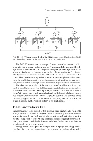
FIGURE 11.2 TF power supply circuit of the T-10 tokamak. L1–L4, TF coil sections; R1–R4,
grounding resistors; TC1–TC4, thyristor converters; Tr1– Tr4, transformers.
The T-10 PS system took advantage of some innovative solutions, which
were later implemented in other machines. These included a modular DC volt-
age source in the form of a TC composed of eight 6-pulse bridge modules. Its
advantage is the ability to considerably reduce the short-circuit effect in case
of a thyristor module breakdown. In addition, the modular configuration makes
it possible to increase the equivalent number of converter phases and to imple-
ment the sophisticated control algorithms. As a result, rectified voltage pulsa-
tion, reactive power consumption and network voltage distortions are reduced.
The alternate connection of the thyristor modules with the coil sections
made it possible to reduce four-fold the requirements for the ground insulation.
A symmetrical scheme of grounding through resistors connected to the ‘neutral
points’ of the converters, with terminals of each coil balanced relative to ground,
had an additional effect: each terminal-to-ground potential was twice as low as
the voltage applied to the coils. In addition, emergency currents at coil short-
circuit to ground can be reduced, as there is no dead ground.
11.2.2 Superconducting Coils
Superconducting coils instead of the resistive ones dramatically reduce the
energy needed to generate a magnetic field. Additional power from external
sources is scarcely required to maintain current in such coils for a lengthy
months-long period of time. All one needs to do is to compensate for insignifi-
cant power losses in resistive busbars and switching devices connected in series
with the coils and in contact joints.
Energy accumulation prior to an experiment campaign and energy extrac-
tion from the coils after completion of the campaign proceed for a long period