
Page 351 - Fundamentals of Magnetic Thermonuclear Reactor Design
P. 351
328 Fundamentals of Magnetic Thermonuclear Reactor Design
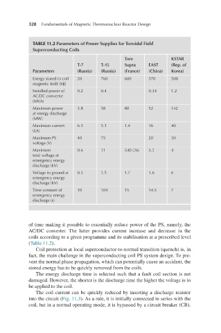
TABLE 11.2 Parameters of Power Supplies for Toroidal Field
Superconducting Coils
Tore KSTAR
T-7 T-15 Supra EAST (Rep. of
Parameters (Russia) (Russia) (France) (China) Korea)
Energy stored in coil 20 760 600 370 500
magnetic field (MJ)
Installed power of 0.2 0.4 0.34 1.2
AC/DC converter
(MVA)
Maximum power 3.8 58 80 52 142
at energy discharge
(MW)
Maximum current 6.3 5.3 1.4 16 40
(kA)
Maximum PS 40 75 20 30
voltage (V)
Maximum 0.6 11 540 (26) 3.2 4
total voltage at
emergency energy
discharge (kV)
Voltage to ground at 0.3 1.5 1.7 1.6 6
emergency energy
discharge (kV)
Time constant of 10 104 15 14.5 7
emergency energy
discharge (s)
of time making it possible to essentially reduce power of the PS, namely, the
AC/DC converter. The latter provides current increase and decrease in the
coils according to a given programme and its stabilisation at a prescribed level
(Table 11.2).
Coil protection at local superconductor-to-normal transition (quench) is, in
fact, the main challenge in the superconducting coil PS system design. To pre-
vent the normal phase propagation, which can potentially cause an accident, the
stored energy has to be quickly removed from the coils.
The energy discharge time is selected such that a fault coil section is not
damaged. However, the shorter is the discharge time the higher the voltage is to
be applied to the coil.
The coil current can be quickly reduced by inserting a discharge resistor
into the circuit (Fig. 11.3). As a rule, it is initially connected in series with the
coil, but in a normal operating mode, it is bypassed by a circuit breaker (CB).