
Page 377 - Fundamentals of Magnetic Thermonuclear Reactor Design
P. 377
Mechanics of Magnetic Fusion Reactors Chapter | 12 355
field coil system, and controlled power supply to the CS and poloidal field coils
at different discharge stages, including potential plasma disruptions. In addi-
tion, there is a coil cooling stage in the superconducting magnet system (MS).
These loads are taken up by load-bearing and support structures.
Gen-1 and Gen-2 tokamaks (T-3, T-7, T-10, TFTR, etc.) employed regular
ring-shaped TFCs, selected for fabrication simplicity. However, the non-uni-
form in-plane ponderomotive forces cause extension and in-plane bending of
the coil. It is therefore reasonable to utilise a D-shaped TFC, satisfying
q ρ = const, qρ=const,
where q is the linear load on the coil and ρ is the coil curvature radius. D-shaped
(or close to being D-shaped) TFCs are used in JET, DOUBLET-III, KSTAR
and other machines. D-shaped TFCs have been chosen for ITER.
The strength criteria are important but not exclusive for selecting the TFC
geometry. The most critical considerations are generally related to plasma phys-
ics factors and operating needs.
The poloidal field and CS coils are ring-shaped: a design feature allowing
accommodation of the axis-symmetrical ponderomotive forces. Radial forces
in toroidal systems are accommodated by either a central support cylinder or
by wedging (‘barrel vault’). In the latter case, a continuous support cylinder is
formed by the TFC’s straight parts. It transforms radial forces directed towards
the tokamak centre into circumferential forces. Actually, a combination of the
two solutions can be used.
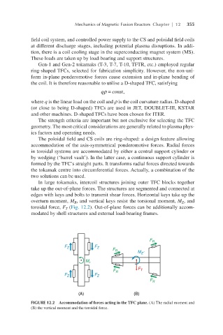
In large tokamaks, intercoil structures joining outer TFC blocks together
take up the out-of-plane forces. The structures are segmented and connected at
edges with keys and bolts to transmit shear forces. Horizontal keys take up the
overturn moment, M , and vertical keys resist the torsional moment, M , and
R
Z
toroidal force, F (Fig. 12.2). Out-of-plane forces can be additionally accom-
T
modated by shell structures and external load-bearing frames.
FIGURE 12.2 Accommodation of forces acting in the TFC plane. (A) The radial moment and
(B) the vertical moment and the toroidal force.