
Page 378 - Fundamentals of Magnetic Thermonuclear Reactor Design
P. 378
356 Fundamentals of Magnetic Thermonuclear Reactor Design
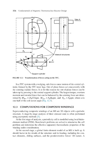
FIGURE 12.3 Transformation of forces acting on the TFC.
In a TFC system with a wedging, side forces cause torsion of the central cyl-
inder, formed by the TFC inner legs. Out-of-plane forces act concurrently with
the centring (radial) forces. It is for this reason the out-of-plane forces can be
taken up by pressing to the central support cylinder. The largest torque, overturn
moment and toroidal force that can be balanced by the centring force are deter-
,
(
MRcr=(FRl/2)tgα, MZ′cr=FRR mined by M Rcr = F l/2) tg α M ′ Zcr = FR tg α, and F Tcr = F tg α , where α is
R 0
R
R
tgα, and FTcr=FRtgα one-half of the coil sector angle (Fig. 12.3).
0
12.3 COMPUTATIONS FOR COMPOSITE WINDINGS
Superconducting composite windings of an MS are 3D objects with a periodic
structure. A stage-by-stage analysis of their stressed state is often performed
using asymptotic methods [5].
At the first stage of analysis, a periodicity cell is modelled using local finite-
element method (FEM). Benchmark problems are solved to structurise the cell
problem and determine the effective (apparent) thermoelastic properties of the
winding under consideration.
At the second stage, a global finite-element model of an MS is built up. It
should factor in the details of the structure and its loading, including the con-
tact elements, sliding surfaces, and the ponderomotive forces’ 3D nature. A