
Page 380 - Fundamentals of Magnetic Thermonuclear Reactor Design
P. 380
358 Fundamentals of Magnetic Thermonuclear Reactor Design
FIGURE 12.5 Finite-element model of the PF1 coil segment. (Copyright ITER Organization,
2017).
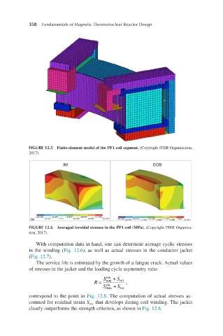
FIGURE 12.6 Averaged toroidal stresses in the PF1 coil (MPa). (Copyright ITER Organiza-
tion, 2017).
With computation data in hand, one can determine average cyclic stresses
in the winding (Fig. 12.6), as well as actual stresses in the conductor jacket
(Fig. 12.7).
The service life is estimated by the growth of a fatigue crack. Actual values
of stresses in the jacket and the loading cycle asymmetry ratio
S em + S
R = min res ,
em
R=Sminem+SresSmaxem+Sres, S max + S res
correspond to the point in Fig. 12.8. The computation of actual stresses ac-
counted for residual strain S that develops during coil winding. The jacket
res
clearly outperforms the strength criterion, as shown in Fig. 12.8.