
Page 66 - Fundamentals of Magnetic Thermonuclear Reactor Design
P. 66
ITER – International Thermonuclear Experimental Reactor Chapter | 3 49
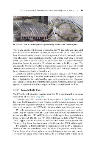
FIGURE 3.8 Part of a radial plate with grooves being machined and a finished plate.
They make an intercoil structure mounted on the VV perimeter and integrated
with the coil cases. Elements of intercoil structures and TF coil cases are iso-
lated from each other to avoid the development of closed electrical circuits.
Thin glass/epoxy resin gaskets and (in the ‘arch-shaped strut’ area) a ceramic
cover layer with a friction coefficient of not less than 0.2 provide necessary
insulation. Spaces for mounting PF coils are provided on the TF coil cases. The
intermetallic Nb Sn-based cable-in-conduit superconductor is made of around
3
1000 strands encased in a stainless-steel jacket of a ∼40 mm diameter. The
jacket also acts as a liquid helium channel.
After being laid, the cable is treated in a vacuum furnace at 650 °C for 200 h,
whereupon the winding is insulated and re-wound. Each turn is wrapped in several
layers of polyimide film and glass fibre tapes impregnated with a mix of cyanate
ester and epoxy resins. Following the impregnation, reinforcing plates are welded
upon each superconducting layer to give additional strength to coil sections.
3.3.2 Poloidal Field Coils
The PF coils with diameters varying from 8 to 20 m are attached to the outer
sides of the TF coil cases (Fig. 3.9).
The coils use a NbTi cable-in-conduit superconductor (Table 3.5). Each coil
has some double pancakes, wound with two parallel conductors encased in steel
conduits with a square outer section. When the tokamak is being assembled, PF
coils are fixed to the cases of TF coils to form a whole load-bearing structure.
PF coils maintenance/repair and replacement procedures are very cumber-
some. Only the upper PF1 and PF2 coils can be extracted and repaired outside of
the cryostat. The lower PF5 and PF6 coils can only be repaired and re-wound when
inside the cryostat. The PF3 and PF4 coils sit between the belts of the VV ports.
These trapped coils are very difficult to access and cannot virtually be replaced.
Therefore, they should function throughout the lifetime of the ITER without repair.
For example, a double interturn insulation is used in the PFC sections. It
consists of two insulation layers separated with a thin-grounded metallic insert.
Such a design allows fixing leakage currents that precede interturn short circuit.
The latter may cause considerable damage to a coil that would require repair