
Page 67 - Fundamentals of Magnetic Thermonuclear Reactor Design
P. 67
50 Fundamentals of Magnetic Thermonuclear Reactor Design
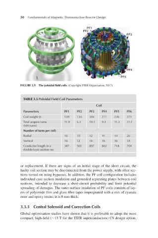
FIGURE 3.9 The poloidal field coils. (Copyright ITER Organization, 2017).
TABLE 3.5 Poloidal Field Coil Parameters
Coil
Parameters PF1 PF2 PF3 PF4 PF5 PF6
Coil weight (t) 139 134 304 277 236 271
Total ampere turns 11.9 6.3 10.2 9.3 11.3 22.1
(MA-turns)
Number of turns per coil:
Radial 16 10 12 11 14 26
Vertical 16 12 16 16 16 18
Conductor length in a 387 501 897 802 718 704
double-layer section (m)
or replacement. If there are signs of an initial stage of the short circuit, the
faulty coil section may be disconnected from the power supply, with other sec-
tions turned on using bypasses. In addition, the PF coil configuration includes
individual case section insulation and grounded separating plates between coil
sections, intended to decrease a short-circuit probability and limit potential
spreading of damages. The outer surface insulation of PF coils consists of lay-
ers of polyimide film and glass fibre tapes impregnated with a mix of cyanate
ester and epoxy resins; it is 8 mm thick.
3.3.3 Central Solenoid and Correction Coils
Global optimisation studies have shown that it is preferable to adopt the most
compact, high-field (∼13 T for the ITER superconductors) CS design option.