
Page 72 - Fundamentals of Magnetic Thermonuclear Reactor Design
P. 72
ITER – International Thermonuclear Experimental Reactor Chapter | 3 55
port, the module is put in a sealed container and transported to a ‘hot chamber’
for maintenance/repair. Similar containers are used to move the HF and UHF
heating antennas and the diagnostics equipment.
3.5.2 Divertor
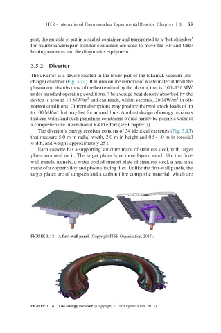
The divertor is a device located in the lower part of the tokamak vacuum (dis-
charge) chamber (Fig. 3.14). It allows online removal of waste material from the
plasma and absorbs most of the heat emitted by the plasma, that is, 100–136 MW
under standard operating conditions. The average heat density absorbed by the
2
2
device is around 10 MW/m and can reach, within seconds, 20 MW/m in off-
normal conditions. Current disruptions may produce thermal shock loads of up
2
to 100 MJ/m that may last for around 1 ms. A robust design of energy receivers
that can withstand such punishing conditions would hardly be possible without
a comprehensive international R&D effort (see Chapter 7).
The divertor’s energy receiver consists of 54 identical cassettes (Fig. 3.15)
that measure 5.0 m in radial width, 2.0 m in height and 0.5–1.0 m in toroidal
width, and weighs approximately 25 t.
Each cassette has a supporting structure made of stainless steel, with target
plates mounted on it. The target plates have three layers, much like the first-
wall panels, namely, a water-cooled support plate of stainless steel, a heat sink
made of a copper alloy and plasma-facing tiles. Unlike the first-wall panels, the
target plates are of tungsten and a carbon fibre composite material, which are
FIGURE 3.13 A first-wall panel. (Copyright ITER Organization, 2017).
FIGURE 3.14 The energy receiver. (Copyright ITER Organization, 2017).