
Page 68 - Fundamentals of Magnetic Thermonuclear Reactor Design
P. 68
ITER – International Thermonuclear Experimental Reactor Chapter | 3 51
If these conditions are met, the CS parameters are far from optimum. Mechani-
cal stresses in the conduit material reach 375 MPa and remain heavy at cryo-
genic temperatures. The requirement for the CS case and load-bearing structure
material is, therefore, primarily a plastic high-strength steel. The material of
choice was the 316LN very low-carbon cold-worked steel.
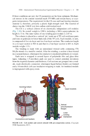
The CS is a vertical column of six electrically independent coil modules
(Fig. 3.10). Its overall weight is 1300 t, including a 260-t superconductor; its
height is 13 m. The outer radius of one winding pack module is 2.07 m.
The column is placed in a vertical ‘pit,’ made up of TF coil rectilinear parts
and rests on pedestals in lower butt-ends of the TF coils. Each module, in turn,
is composed of five six-layer and two four-layer sections. The conductor length
in a six-layer section is 903 m and that in a four-layer section is 601 m. Each
module weighs 115 t.
The winding is made with an uninsulated twisted cable containing 576
Nb Sn strands in a metallic conduit. After the winding, a section is heat treated
3
in a vacuum furnace, whereupon the conductor is insulated and finally re-wound.
Each turn is wrapped in several layers of polyimide film and glass fibre
tapes. Adjusting 1.5-mm-thick pads are used to correct potential deviations
from the required diameter and thickness. Coil sections are grouped into a mod-
ule, made electrically connected, whereupon liquid helium feeders are formed
and a 10-mm-thick coil case insulation wrapping is made. An insulated module
is impregnated with epoxy resin.
FIGURE 3.10 Coil module and central solenoid with pre-compression system. (Copyright
ITER Organization, 2017).