
Page 74 - Fundamentals of Magnetic Thermonuclear Reactor Design
P. 74
ITER – International Thermonuclear Experimental Reactor Chapter | 3 57
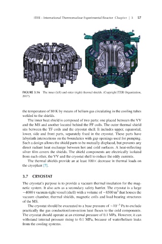
FIGURE 3.16 The inner (left) and outer (right) thermal shields. (Copyright ITER Organization,
2017).
the temperature of 80 K by means of helium gas circulating in the cooling tubes
welded to the shields.
The inner heat shield is composed of two parts: one placed between the VV
and the MS and another located behind the PF coils. The outer thermal shield
sits between the TF coils and the cryostat shell. It includes upper, equatorial,
lower, side and front parts, separately fixed in the cryostat. These parts have
labyrinth intersections on the boundaries with gap openings used for pumping.
Such a design allows the shield parts to be mutually displaced, but prevents any
direct radiant heat exchange between hot and cold surfaces. A heat-reflecting
silver film covers the shields. The shield components are electrically isolated
from each other, the VV and the cryostat shell to reduce the eddy currents.
The thermal shields provide an at least 100× decrease in thermal loads on
the cryoplant [7].
3.7 CRYOSTAT
The cryostat’s purpose is to provide a vacuum thermal insulation for the mag-
netic system. It also acts as a secondary safety barrier. The cryostat is a large
3
∼4000 t vacuum-tight vessel (shell) with a volume of ∼8500 m that houses the
vacuum chamber, thermal shields, magnetic coils and load-bearing structures
of the MS.
−3
The cryostat should be evacuated to a base pressure of ∼10 Pa to exclude
practically the gas conduction/convection heat fluxes to the cold components.
The cryostat should operate at an external pressure of 0.1 MPa. However, it can
withstand internal pressure rising to 0.1 MPa, because of water/helium leaks
from the cooling systems.