
Page 100 - Fundamentals of Radar Signal Processing
P. 100
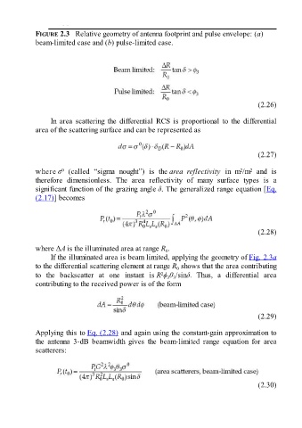
FIGURE 2.3   Relative geometry of antenna footprint and pulse envelope: (a)
               beam-limited case and (b) pulse-limited case.


                                                                                                       (2.26)

                     In  area  scattering  the  differential  RCS  is  proportional  to  the  differential
               area of the scattering surface and can be represented as


                                                                                                       (2.27)


               where σ   (called  “sigma  nought”)  is  the area  reflectivity  in  m /m   and  is
                         0
                                                                                                2
                                                                                                    2
               therefore  dimensionless.  The  area  reflectivity  of  many  surface  types  is  a
               significant function of the grazing angle δ. The generalized range equation [Eq.
               (2.17)] becomes


                                                                                                       (2.28)

               where ΔA is the illuminated area at range R .
                                                                  0
                     If the illuminated area is beam limited, applying the geometry of Fig. 2.3a

               to the differential scattering element at range R  shows that the area contributing
                                                                       0
                                                                2
               to  the  backscatter  at  one  instant  is R ϕ θ /sinδ.  Thus,  a  differential  area
                                                                   3 3
               contributing to the received power is of the form


                                                                                                       (2.29)

               Applying this to Eq. (2.28) and again using the constant-gain approximation to
               the  antenna  3-dB  beamwidth  gives  the  beam-limited  range  equation  for  area
               scatterers:


                                                                                                       (2.30)