
Page 217 - Fundamentals of Radar Signal Processing
P. 217
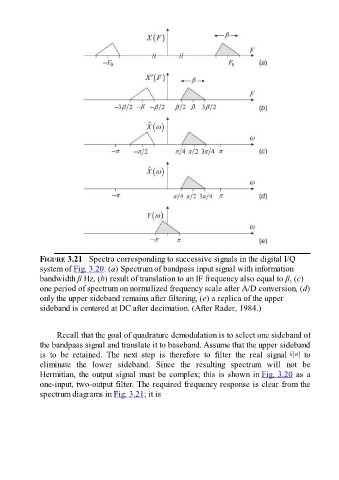
FIGURE 3.21   Spectra corresponding to successive signals in the digital I/Q
               system of Fig. 3.20. (a) Spectrum of bandpass input signal with information
               bandwidth β Hz, (b) result of translation to an IF frequency also equal to β, (c)
               one period of spectrum on normalized frequency scale after A/D conversion, (d)

               only the upper sideband remains after filtering, (e) a replica of the upper
               sideband is centered at DC after decimation. (After Rader, 1984.)


                     Recall that the goal of quadrature demodulation is to select one sideband of
               the bandpass signal and translate it to baseband. Assume that the upper sideband
               is  to  be  retained.  The  next  step  is  therefore  to  filter  the  real  signal         to
               eliminate  the  lower  sideband.  Since  the  resulting  spectrum  will  not  be
               Hermitian, the output signal must be complex; this is shown in Fig. 3.20 as a

               one-input, two-output filter. The required frequency response is clear from the
               spectrum diagrams in Fig. 3.21; it is