
Page 218 - Fundamentals of Radar Signal Processing
P. 218
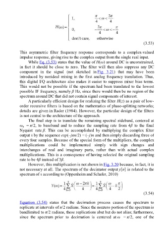
(3.53)

               This  asymmetric  filter  frequency  response  corresponds  to  a  complex-valued

               impulse response, giving rise to the complex output from the single real input.
                     While Eq. (3.53) states that the value of H(ω) around DC is unconstrained,
               in  fact  it  should  be  close  to  zero.  The  filter  will  then  also  suppress  any  DC
               component  in  the  signal  (not  sketched  in Fig.  3.21)  that  may  have  been
               introduced by nonideal mixing in the first analog frequency translation. Thus,
               this digital I/Q architecture also makes it easier to suppress mixer bias terms.

               This would not be possible if the spectrum had been translated to the lowest
               possible IF frequency, namely β Hz, since there would then be no region of the
               spectrum around DC that did not contain signal components of interest.
                     A particularly efficient design for realizing the filter H(z) as a pair of low-
               order recursive filters is based on the mathematics of phase-splitting networks;
               details are given in Rader (1984). However, the particular design of the filters
               is not central to the architecture of the approach.

                     The final step is to translate the remaining spectral sideband, centered at
               ω   = π/2,  to  baseband  and  to  reduce  the  sampling  rate  from  4β  to  the  final
                 0
               Nyquist  rate β.  This  can  be  accomplished  by  multiplying  the  complex  filter
               output   by the sequence exp(–jπn/2) = (–j)n and then simply discarding three of
               every four samples. Because of the special form of the multipliers, the complex
               multiplications  could  be  implemented  simply  with  sign  changes  and

               interchanges  of  real  and  imaginary  parts,  rather  than  with  actual  complex
               multiplications. This is a consequence of having selected the original sampling
               rate to be 4β instead of 3β.
                     However, this multiplication is not shown in Fig. 3.20 because, in fact, it is
               not necessary at all. The spectrum of the decimator output y[n] is related to the
               spectrum of   according to (Oppenheim and Schafer, 2010)


                                                                                                       (3.54)

               Equation  (3.54)  states  that  the  decimation  process  causes  the  spectrum  to
               replicate at intervals of π/2 radians. Since the nonzero portion of the spectrum is
               bandlimited to π/2 radians, these replications abut but do not alias; furthermore,
               since  the  spectrum  prior  to  decimation  is  centered  at ω  = π/2,  one  of  the