
Page 219 - Fundamentals of Radar Signal Processing
P. 219
replications (k = 3, specifically) is centered at ω = 2π radians. The periodicity
of the spectrum of a discrete-time signal therefore guarantees that there is a
replica centered at ω = 0 as well; this replica is the final desired spectrum.
Thus, the real and imaginary outputs of the decimator are the desired I and Q
signals. Another digital I/Q system that uses the spectrum replicating properties
of decimation to advantage is described in Rice and Wu (1982).
The success of the decimation operation in eliminating the need for a final
complex frequency translation depended on the proper relationship between the
bandwidth and center frequency of the signal, and the decimation factor. This is
the major reason for choosing the IF to be β instead of β/2 (or some other
permissible value), and the sampling frequency as 4β instead of 3β (or some
other value).
Rader’s digital I/Q architecture has reduced the number of analog signal
channels from two to one, making the issues of oscillator quadrature and gain
and phase matching completely moot, while also providing a natural opportunity
to filter out DC biases introduced by the remaining analog mixer. Furthermore,
the two A/D converters required at the output of the conventional quadrature
receiver to enable subsequent digital processing have been reduced to one.
There are two major costs to these improvements. The first is an increase by a
factor of four in the A/D converter speed requirement, from β samples per
second for conventional baseband sampling to 4β samples per second for
Rader’s system; this may be difficult at radar signal bandwidths. The second is
the introduction of the need for high-rate digital filtering, which is
computationally expensive (although Rader’s efficient filter design lessens this
cost).
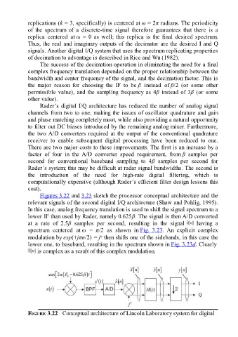
Figures 3.22 and 3.23 sketch the processor conceptual architecture and the
relevant signals of the second digital I/Q architecture (Shaw and Pohlig, 1995).
In this case, analog frequency translation is used to shift the signal spectrum to a
lower IF than used by Rader, namely 0.625β. The signal is then A/D converted
at a rate of 2.5β samples per second, resulting in the signal having a
spectrum centered at ω = π/2 as shown in Fig. 3.23. An explicit complex
n
modulation by exp(+jπn/2) = j then shifts one of the sidebands, in this case the
lower one, to baseband, resulting in the spectrum shown in Fig. 3.23d. Clearly
is complex as a result of this complex modulation.
FIGURE 3.22 Conceptual architecture of Lincoln Laboratory system for digital