
Page 260 - Fundamentals of Radar Signal Processing
P. 260
remained M pulses long as discussed above, there would be P consecutive
spikes with the full amplitude of 1.0, similar to Fig. 4.16a.
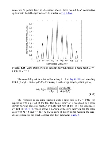
FIGURE 4.18 Zero-Doppler cut of the ambiguity function of a pulse burst. M =
5 pulses, T = 4τ.
The zero delay cut is obtained by setting t = 0 in Eq. (4.78) and recalling
that A (0, F ) = |sin(πF τ)/πF τ|(assuming a unit energy simple pulse), giving
D
D
p
D
(4.80)
The response is an asinc function with a first zero at F = 1/MT Hz,
D
repeating with a period of 1/T Hz. This basic behavior is weighted by a more
slowly varying true sinc function with its first zero at 1/τ Hz. This structure is
evident in Fig. 4.19, which shows a portion of the zero delay cut for the same
case with M = 5 and T = 4τ. The 1/T spacing of the principal peaks in the zero-
delay response is the blind Doppler shift first defined in Chap. 3.