
Page 383 - Fundamentals of Radar Signal Processing
P. 383
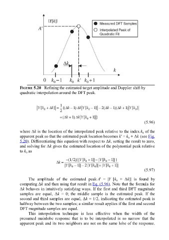
FIGURE 5.20   Refining the estimated target amplitude and Doppler shift by
               quadratic interpolation around the DFT peak.


                                                                                                       (5.96)

               where Δk is the location of the interpolated peak relative to the index k  of the
                                                                                                     0
               apparent peak so that the estimated peak location becomes k′ = k  + Δk (see Fig.
                                                                                           0
               5.20). Differentiating this equation with respect to Δk, setting the result to zero,
               and solving for Δk gives the estimated location of the polynomial peak relative

               to k  as
                   0


                                                                                                       (5.97)

                     The  amplitude  of  the  estimated  peak A′  =  |Y  [k   +  Δk]|  is  found  by
                                                                                   0
               computing Δk and then using that result in Eq. (5.96). Note that the formula for
               Δk behaves in intuitively satisfying ways. If the first and third DFT magnitude
               samples  are  equal,  Δk  =  0;  the  middle  sample  is  the  estimated  peak.  If  the
               second and third samples are equal, Δk = 1/2, indicating the estimated peak is

               halfway between the two samples; a similar result applies if the first and second
               DFT magnitude samples are equal.
                     This  interpolation  technique  is  less  effective  when  the  width  of  the
               presumed  mainlobe  response  that  is  to  be  interpolated  is  so  narrow  that  the
               apparent peak and its two neighbors are not on the same lobe of the response.