
Page 395 - Fundamentals of Radar Signal Processing
P. 395
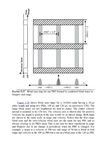
FIGURE 5.27   Blind zone map for one PRF formed by combined blind zones in
               Doppler and range.


                     Figure 5.28 shows blind zone maps for a 10-GHz radar having a 10-μs

               pulse length and using two PRIs, 100 μs and 120 μs, on successive CPIs. The
               range  blind  zones  are  not  lengthened  for  near-in  clutter.  The  clutter  velocity
               spread is assumed to be ±20 m/s. The velocity axis is shown only for positive
               velocity; the negative portion of the axis would be its mirror image. Both maps
               are shown to the same scale in range and velocity. Notice that the first range
               blind zone and the zero-velocity blind zone are the same for any PRF and so
               always overlap in all PRFs used. This is not true for their repetitions in range
               and  Doppler  due  to  the  change  in  periodicity  when  the  PRF  is  changed.  For

               example, a target at a velocity of 300 m/s and range of 30 km is blind in both
               range and velocity at the 100-μs PRI but is not in a blind zone at the 120-μs PRI.