
Page 428 - Fundamentals of Radar Signal Processing
P. 428
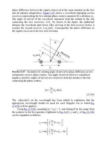
phase difference between the signals observed at the same moment on the fore

               and aft antenna subapertures. Figure 5.47 shows a wavefront impinging on two
               receivers representing the two antenna phase centers separated by a distance d .
                                                                                                            pc
               The  angle  of  arrival  of  the  wavefront,  measured  from  the  normal  to  the  line
               connecting  the  two  receivers,  is θ .  As  shown  in  the  figure,  the  additional
                                                          a
               distance the wavefront must travel after arriving at the first receiver before it
               reaches  the  second  receiver  is d sinθ . Consequently, the phase difference in
                                                             a
                                                       pc
               the signals received at the two sites becomes


               FIGURE 5.47   Geometry for relating angle of arrival to phase difference at two
               subaperture receive phase centers. The angle of arrival shown is considered
               negative; positive angles of arrival are clockwise from the normal to the line

               connecting the phase centers.


                                                                                                     (5.139)


               The  subscript k  on  the  wavelength  has  been  added  to  emphasize  that  the

               appropriate  wavelength  should  be  used  for  each  Doppler  bin  to  which Eq.
               (5.139) will be applied.
                     Using Eq. (5.139), assuming |γ | = |γ | = 1, and letting R be the range from
                                                                a
                                                          f
               the scatterer to the fore aperture (rightmost in Fig. 5.47), γ  and γ  of Eq. (5.138)
                                                                                           a
                                                                                    f
               can be expanded as follows