
Page 425 - Fundamentals of Radar Signal Processing
P. 425
if the T-R1 phase center is at position x + d /2 on the first pulse, then M s
0
pc
pulses later the T-R2 transmit phase center will be at position x – d /2 + vM T.
s
0
pc
Equating these two positions gives
(5.134)
M is the “time slip” in pulses.
s
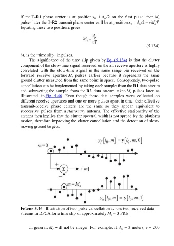
The significance of the time slip given by Eq. (5.134) is that the clutter
component of the slow-time signal received on the aft receive aperture is highly
correlated with the slow-time signal in the same range bin received on the
forward receive aperture M pulses earlier because it represents the same
s
ground clutter measured from the same point in space. Consequently, two-pulse
cancellation can be implemented by taking each sample from the R1 data stream
and subtracting the sample from the R2 data stream taken M pulses later as
s
illustrated in Fig. 5.46. Even though these data samples were collected on
different receive apertures and one or more pulses apart in time, their effective
transmit-receive phase centers are the same so they appear equivalent to
successive pulses from a stationary antenna. The effective stationarity of the
antenna then implies that the clutter spectral width is not spread by the platform
motion, therefore improving the clutter cancellation and the detection of slow-
moving ground targets.
FIGURE 5.46 Illustration of two-pulse cancellation across two received data
streams in DPCA for a time slip of approximately M = 3 PRIs.
s
In general, M will not be integer. For example, if d = 3 meters, v = 200
s
pc