
Page 422 - Fundamentals of Radar Signal Processing
P. 422
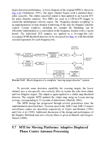
target detection performance. A block diagram of the original MTD is shown in

               Fig. 5.43 (Nathanson, 1991). The upper channel begins with a standard three-
               pulse canceller. The clutter-cancelled output is then applied to an 8-point FFT
               for  pulse  Doppler  analysis.  Two  PRFs  are  used  in  a  CPI-to-CPI  stagger  to
               extend the unambiguous velocity region. The “frequency domain weighting” is
               an implementation of time-domain windowing of the data for Doppler sidelobe
               control.  Certain  windows,  including  for  example  the  Hamming,  can  be

               efficiently implemented as a convolution in the frequency domain with a 3-point
               kernel.  The  individual  FFT  samples  are  applied  to  a  16-range-bin  cell-
               averaging CFAR threshold detector (to be discussed in Chap. 6) with thresholds
               selected separately for each frequency bin.


               FIGURE 5.43   Block diagram of a complete “moving target detector” system.


                     To  provide  some  detection  capability  for  crossing  targets,  the  lower

               channel uses a site-specific zero-velocity filter to isolate the echo from clutter
               and low-Doppler targets. The output is again applied to a clutter map threshold
               detector.  The  original  MTD  updated  the  clutter  map  using  an  8-scan  moving
               average, corresponding to 32 seconds of data history (Skolnik, 2001).
                     The  MTD  design  has  progressed  through  several  generations  since  the
               implementation described here. Versions used in the ASR-9 and ASR-12 airport
               surveillance  radars  are  described  respectively  in  Taylor  and  Brunins  (1985)

               and Cole et al (1998). Additional discussion of the design and performance of
               the Doppler filterbank and zero-velocity filters is given in Shrader and Gregers-
               Hansen (2008).


               5.7   MTI for Moving Platforms: Adaptive Displaced
                        Phase Center Antenna Processing