
Page 146 - Fundamentals of Reservoir Engineering
P. 146
MATERIAL BALANCE APPLIED TO OIL RESERVOIRS 85
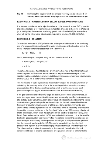
Fig. 3.5 Illustrating two ways in which the primary recovery can be enhanced; by
downdip water injection and updip injection of the separated solution gas
EXERCISE 3.3 WATER INJECTION BELOW BUBBLE POINT PRESSURE
It is planned to initiate a water injection scheme in the reservoir whose PVT properties
are defined in table 2.4. The intention is to maintain pressure at the level of 2700 psia
(p b = 3330 psia). If the current producing gas oil ratio of the field (R) is 3000 scf/stb,
what will be the initial water injection rate required to produce 10,000 stb/d of oil.
EXERCISE 3.3 SOLUTION
To maintain pressure at 2700 psia the total underground withdrawal at the producing
end of a reservoir block must equal the water injection rate at the injection end of the
block. The total withdrawal associated with 1 stb of oil is
rb
B o + (R − R s)B g
which, evaluating at 2700 psia, using the PVT data in table 2.4, is
1.2022 + (3000 − 401) 0.00107
= 4.0 rb
Therefore, to produce 10,000 stb/d oil, an initial injection rate of 40,000 rb/d of water
will be required, 70% of which will be needed to displace the liberated gas. If the
injection had been started at, or above bubble point pressure, a maximum injection rate
of only 12,500 b/d of water would have been required.
The mechanics of water injection are described in Chapter 10, including methods of
calculating the recovery factor. One of the advantages in this secondary recovery
process is that if the displacement is maintained at, or just below, bubble point
pressure the producing gas oil ratio is constant and approximately equal to R si.
If the gas quantities are sufficiently large it is easier, under these circumstances, to
enter into a gas sales contract in which gas rates are usually specified by the customer
at a plateau level. Conversely, there are obvious difficulties attached to entering such a
contract with a gas oil ratio profile as shown in fig. 3.4. In such cases difficulties are
frequently encountered in disposing of all the gas. Some portion of it may be sold
under a fixed contract agreement but the remainder, which is frequently unpredictable
in quantity, presents problems. In the "old days" (prior to the 1973−energy crisis) a lot
of this excess gas, which could not conveniently be used as a local fuel supply, was
flared. Even as late as the end of 1973 it was estimated that some 11% of the world's
total daily gas production was flared. Today, regulations concerning gas disposal are
more stringent and in many cases operators are obliged to re-inject excess gas back
into the reservoir as shown in fig. 3.5. The gas is separated from the oil at high
pressure and injected at a structurally high point thus forming a secondary gas cap.
The oil production is taken from downdip in the reservoir thus allowing the high
compressibility gas to expand and displace an equivalent amount of oil towards the