
Page 148 - Fundamentals of Reservoir Engineering
P. 148
MATERIAL BALANCE APPLIED TO OIL RESERVOIRS 87
exploration
well
production wells GAS
( mNB - rb)
oi
GOC
OIL ( NB - rb)
oi
OWC
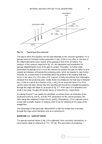
Fig. 3.6 Typical gas drive reservoir
The way in which this equation can be used depends on the unknown quantities. For a
gascap reservoir the least certain parameter in equ. (3.24) is very often m, the ratio of
the initial hydrocarbon pore volume of the gascap to that of the oil column. For
instance, in the reservoir depicted in fig. 3.6, the exploration well penetrated the
gascap establishing the level of the gas oil contact. Thereafter, no further wells
penetrated the gascap since it is not the intention to produce this gas but rather to let it
expand and displace oil towards the producing wells, which are spaced in rows further
downdip. As. a result there is uncertainty about the position of the sealing fault and
hence in the value of m. The value of N, however, is fairly well defined from information
obtained from the producing wells. Under these circumstances the best way to interpret
equ. (3.24) is to plot F as a function of (E o + mE g) for an assumed value of m. If the
correct value has been chosen then the resulting plot should be a straight line passing
through the origin with slope N, as shown in fig. 3.7. If the value of m selected is too
small or too large, the plot will deviate above or below the line, respectively.
In making this plot F can readily be calculated, at various times, as a function of the
production terms N p and R p, and the PVT parameters for the current pressure, the
latter being also required to determine E o and E g. Alternatively, if N is unknown and m
known with a greater degree of certainty, then N can be obtained as the slope of the
straight line.
One advantage of this particular interpretation is that the straight line must pass
through the origin which therefore acts as a control point.
EXERCISE 3.4 GASCAP DRIVE
The gascap reservoir shown in fig. 3.6 is estimated, from volumetric calculations, to
6
have had an initial oil volume N of 115 × 10 stb. The cumulative oil production