
Page 235 - Fundamentals of Reservoir Engineering
P. 235
OILWELL TESTING 173
r
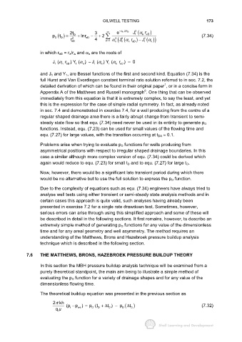
2t 3 ∞ e − α n 2t D J 1 2 (α n eD )
t
p D () = D + lnr eD − + 2 (7.34)
D
2
( ))
r eD 4 n1 α n 2 ( 1 2 (α n eD ) J α n
2
J
r
−
1
=
in which r eD = r e/r w and α n are the roots of
J 1 (α n r ) Y 1 (α n ) − J 1 (α n ) Y 1 (α n r ) = 0
eD
eD
and J 1 and Y 1, are Bessel functions of the first and second kind. Equation (7.34) is the
full Hurst and Van Everdingen constant terminal rate solution referred to in sec. 7.2, the
1
detailed derivation of which can be found in their original paper , or in a concise form in
6
Appendix A of the Matthews and Russell monograph . One thing that can be observed
immediately from this equation is that it is extremely complex, to say the least, and yet
this is the expression for the case of simple radial symmetry. In fact, as already noted
in sec. 7.4 and demonstrated in exercise 7.4, for a well producing from the centre of a
regular shaped drainage area there is a fairly abrupt change from transient to semi-
steady state flow so that equ. (7.34) need never be used in its entirity to generate p D
functions. Instead, equ. (7.23) can be used for small values of the flowing time and
equ. (7.27) for large values, with the transition occurring at t DA ≈ 0.1.
Problems arise when trying to evaluate p D functions for wells producing from
asymmetrical positions with respect to irregular shaped drainage boundaries. In this
case a similar although more complex version of equ. (7.34) could be derived which
again would reduce to equ. (7.23) for small t D and to equ. (7.27) for large t D.
Now, however, there would be a significant late transient period during which there
would be no alternative but to use the full solution to express the p D function.
Due to the complexity of equations such as equ. (7.34) engineers have always tried to
analyse well tests using either transient or semi-steady state analysis methods and in
certain cases this approach is quite valid, such analyses having already been
presented in exercise 7.2 for a single rate drawdown test. Sometimes, however,
serious errors can arise through using this simplified approach and some of these will
be described in detail in the following sections. It first remains, however, to describe an
extremely simple method of generating p D functions for any value of the dimensionless
time and for any areal geometry and well asymmetry. The method requires an
understanding of the Matthews, Brons and Hazebroek pressure buildup analysis
technique which is described in the following section.
7.6 THE MATTHEWS, BRONS, HAZEBROEK PRESSURE BUILDUP THEORY
In this section the MBH pressure buildup analysis technique will be examined from a
purely theoretical standpoint, the main aim being to illustrate a simple method of
evaluating the p D function for a variety of drainage shapes and for any value of the
dimensionless flowing time.
The theoretical buildup equation was presented in the previous section as
2kh
π
(p − p ) = p (t + ∆ t ) − p D ( t ∆ D ) (7.32)
D
D
D
i
ws
qµ