
Page 294 - Fundamentals of The Finite Element Method for Heat and Fluid Flow
P. 294
SOME EXAMPLES OF FLUID FLOW AND HEAT TRANSFER PROBLEMS
286
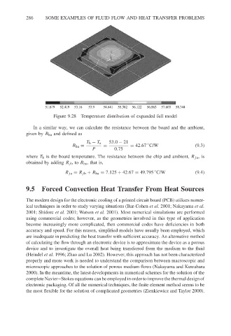
51.679 52.419 53.16 53.9 54.641 55.382 56.122 56.863 57.603 58.344
Figure 9.28 Temperature distribution of expanded full model
In a similar way, we can calculate the resistance between the board and the ambient,
given by R ba and defined as
T b − T a 53.0 − 21
◦
R ba = = = 42.67 C/W (9.3)
P 0.75
where T b is the board temperature. The resistance between the chip and ambient, R ja ,is
obtained by adding R jb to R ba ,thatis,
◦
R ja = R jb + R ba = 7.125 + 42.67 = 49.795 C/W (9.4)
9.5 Forced Convection Heat Transfer From Heat Sources
The modern design for the electronic cooling of a printed circuit board (PCB) utilizes numer-
ical techniques in order to study varying situations (Bar-Cohen et al. 2001; Nakayama et al.
2001; Shidore et al. 2001; Watson et al. 2001). Most numerical simulations are performed
using commercial codes; however, as the geometries involved in this type of application
become increasingly more complicated, then commercial codes have deficiencies in both
accuracy and speed. For this reason, simplified models have usually been employed, which
are inadequate in predicting the heat transfer with sufficient accuracy. An alternative method
of calculating the flow through an electronic device is to approximate the device as a porous
device and to investigate the overall heat being transferred from the medium to the fluid
(Heindel et al. 1996; Zhao and Lu 2002). However, this approach has not been characterized
properly and more work is needed to understand the comparison between macroscopic and
microscopic approaches to the solution of porous medium flows (Nakayama and Kuwahara
2000). In the meantime, the latest developments in numerical schemes for the solution of the
complete Navier–Stokes equations can be employed in order to improve the thermal design of
electronic packaging. Of all the numerical techniques, the finite element method seems to be
the most flexible for the solution of complicated geometries (Zienkiewicz and Taylor 2000).