
Page 299 - Fundamentals of The Finite Element Method for Heat and Fluid Flow
P. 299
SOME EXAMPLES OF FLUID FLOW AND HEAT TRANSFER PROBLEMS
(a) q = 0°, Re = 100 (b) q = 0°, Re = 200 (c) q = 0°, Re = 300 291
(d) q = 10°, Re = 100 (e) q = 10°, Re = 200 (f) q = 10°, Re = 300
(g) q = 20°, Re = 100 (h) q = 20°, Re = 200 (f) q = 20°, Re = 300
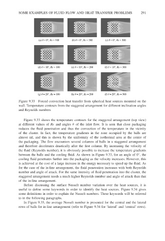
Figure 9.33 Forced convection heat transfer from spherical heat sources mounted on the
wall. Temperature contours from the staggered arrangement for different inclination angles
and Reynolds numbers
Figure 9.33 shows the temperature contours for the staggered arrangement (top view)
at different values of Re and angles θ of the inlet flow. It is seen that close packaging
reduces the fluid penetration and thus the convection of the temperature in the vicinity
of the cluster. In fact, the temperature gradients in the zone occupied by the balls are
almost nil, and this is shown by the uniformity of the isothermal area at the centre of
the packaging. The flow encounters several columns of balls in a staggered arrangement
and therefore decelerates drastically after the first column. By increasing the velocity of
the fluid (Reynolds number), it is obviously possible to increase the temperature gradients
between the balls and the cooling fluid. As shown in Figure 9.33, for an angle of 0 ,the
◦
cooling fluid penetrates further into the packaging as the velocity increases. However, this
is achieved at the cost of a large increase in the energy necessary to speed up the fluid. As
for the case of the in-line arrangement, the fluid penetration increases with both Reynolds
number and angle of attack. For the same intensity of fluid penetration into the cluster, the
staggered arrangement needs a much higher Reynolds number and angle of attack than that
of the in-line arrangement.
Before discussing the surface Nusselt number variation over the heat sources, it is
useful to define some keywords in order to identify the heat sources. Figure 9.34 gives
some definitions in order to explain the Nusselt numbers. These keywords will be referred
to in the following paragraphs.
In Figure 9.35, the average Nusselt number is presented for the central and the lateral
rows of balls for in-line arrangement (refer to Figure 9.34 for ‘lateral’ and ‘central’ rows).