
Page 298 - Fundamentals of The Finite Element Method for Heat and Fluid Flow
P. 298
SOME EXAMPLES OF FLUID FLOW AND HEAT TRANSFER PROBLEMS
290
where A s represents the surface area of each solder ball (s = 1,... , 25 for in-line and
s = 1,... , 41 for staggered arrangements) and n represents the value of the outgoing
normal at each triangular face on the surface of the spheres. The integral term written
above has been calculated numerically by summing the constant (linear elements) values
of the gradient at each surface element multiplied by its area. The values of the Nusselt
number, Nu s , have been calculated for each and every sphere, which are used in both the
in-line and the staggered arrangements, and comparisons are made for different Re and θ.
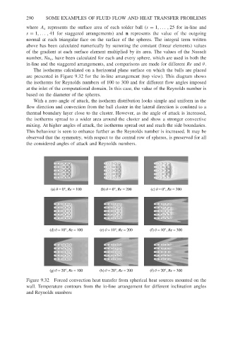
The isotherms calculated on a horizontal plane surface on which the balls are placed
are presented in Figure 9.32 for the in-line arrangement (top view). This diagram shows
the isotherms for Reynolds numbers of 100 to 300 and for different flow angles imposed
at the inlet of the computational domain. In this case, the value of the Reynolds number is
based on the diameter of the spheres.
With a zero angle of attack, the isotherm distribution looks simple and uniform in the
flow direction and convection from the ball cluster in the lateral direction is confined to a
thermal boundary layer close to the cluster. However, as the angle of attack is increased,
the isotherms spread to a wider area around the cluster and show a stronger convective
mixing. At higher angles of attack, the isotherms spread out and reach the side boundaries.
This behaviour is seen to enhance further as the Reynolds number is increased. It may be
observed that the symmetry, with respect to the central row of spheres, is preserved for all
the considered angles of attack and Reynolds numbers.
(a) q = 0°, Re = 100 (b) q = 0°, Re = 200 (c) q = 0°, Re = 300
(d) q = 10°, Re = 100 (e) q = 10°, Re = 200 (f) q = 10°, Re = 300
(g) q = 20°, Re = 100 (h) q = 20°, Re = 200 (f) q = 20°, Re = 300
Figure 9.32 Forced convection heat transfer from spherical heat sources mounted on the
wall. Temperature contours from the in-line arrangement for different inclination angles
and Reynolds numbers