
Page 296 - Fundamentals of The Finite Element Method for Heat and Fluid Flow
P. 296
SOME EXAMPLES OF FLUID FLOW AND HEAT TRANSFER PROBLEMS
288
This arrangement is obtained by cutting the spheres with the horizontal wall (board) on
which the balls are placed. The diameter of the spheres is considered to be equal to 1,
and the distance between the ball centres and the plane that represents the circuit board
is equal to 0.35, as can be seen from Figure 9.29(a). Figure 9.29 also shows the sketch
of the staggered arrangement considered (Figure 9.29(b)). This is obtained by introducing
another partial sphere at the centre of the space between the four in-line spheres.
The flow is assumed to enter the channel from a vertical section (plane y − z), which
is placed at a distance of six diameters upstream of the centres of the first column of
spheres (Figure 9.29(a)). The velocity at the inlet is assumed to be constant at a value of
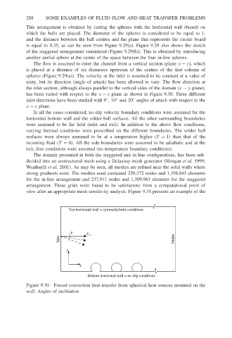
unity, but its direction (angle of attack) has been allowed to vary. The flow direction at
the inlet section, although always parallel to the vertical sides of the domain (x − y plane),
has been varied with respect to the x − z plane as shown in Figure 9.30. Three different
◦
◦
inlet directions have been studied with 0 ,10 and 20 angles of attack with respect to the
◦
x − z plane.
In all the cases considered, no-slip velocity boundary conditions were assumed for the
horizontal bottom wall and the solder ball surfaces. All the other surrounding boundaries
were assumed to be far field (inlet and exit). In addition to the above flow conditions,
varying thermal conditions were prescribed on the different boundaries. The solder ball
surfaces were always assumed to be at a temperature higher (T = 1) than that of the
incoming fluid (T = 0). All the side boundaries were assumed to be adiabatic and at the
exit, free conditions were assumed (no temperature boundary conditions).
The domain presented in both the staggered and in-line configurations, has been sub-
divided into an unstructured mesh using a Delaunay mesh generator (Morgan et al. 1999;
Weatherill et al. 2001). As may be seen, all meshes are refined near the solid walls where
strong gradients exist. The meshes used contained 250,372 nodes and 1,398,845 elements
for the in-line arrangement and 237,911 nodes and 1,309,963 elements for the staggered
arrangement. These grids were found to be satisfactory from a computational point of
view after an appropriate mesh sensitivity analysis. Figure 9.31 presents an example of the
Top horizontal wall = symmetry/inlet conditions
q U ∝
Inlet Outlet
y
x
Bottom horizontal wall = no-slip conditions
Figure 9.30 Forced convection heat transfer from spherical heat sources mounted on the
wall. Angles of inclination