
Page 301 - Fundamentals of The Finite Element Method for Heat and Fluid Flow
P. 301
SOME EXAMPLES OF FLUID FLOW AND HEAT TRANSFER PROBLEMS
8
Row
Re
Row
Re
100 - Central
100 - Lateral 8 100 - Central 293
100 - Lateral
6 200 - Central 6 200 - Central
200 - Lateral 200 - Lateral
300 - Central 300 - Central
Nu 4 300 - Lateral Nu 4 300 - Lateral
2 2
0 0
1st 2nd 3rd 4th 5th 1st 2nd 3rd 4th 5th
Column Column
(a) q = 0°, inline (b) q = 10°, inline
8
6
Re
Nu 4 100 - Central
Row
100 - Lateral
200 - Central
2 200 - Lateral
300 - Central
300 - Lateral
0
1st 2nd 3rd 4th 5th
Column
(c) q = 20°, inline
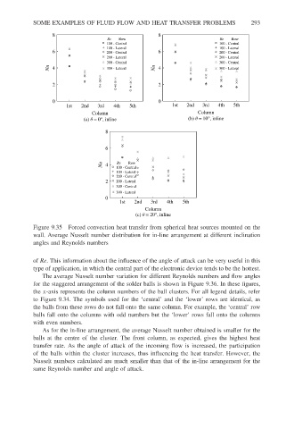
Figure 9.35 Forced convection heat transfer from spherical heat sources mounted on the
wall. Average Nusselt number distribution for in-line arrangement at different inclination
angles and Reynolds numbers
of Re. This information about the influence of the angle of attack can be very useful in this
type of application, in which the central part of the electronic device tends to be the hottest.
The average Nusselt number variation for different Reynolds numbers and flow angles
for the staggered arrangement of the solder balls is shown in Figure 9.36. In these figures,
the x-axis represents the column numbers of the ball clusters. For all legend details, refer
to Figure 9.34. The symbols used for the ‘central’ and the ‘lower’ rows are identical, as
the balls from these rows do not fall onto the same column. For example, the ‘central’ row
balls fall onto the columns with odd numbers but the ‘lower’ rows fall onto the columns
with even numbers.
As for the in-line arrangement, the average Nusselt number obtained is smaller for the
balls at the centre of the cluster. The front column, as expected, gives the highest heat
transfer rate. As the angle of attack of the incoming flow is increased, the participation
of the balls within the cluster increases, thus influencing the heat transfer. However, the
Nusselt numbers calculated are much smaller than that of the in-line arrangement for the
same Reynolds number and angle of attack.