
Page 300 - Fundamentals of The Finite Element Method for Heat and Fluid Flow
P. 300
SOME EXAMPLES OF FLUID FLOW AND HEAT TRANSFER PROBLEMS
292
Lateral row
Flow
Inlet Central row Outlet
z
First column
x
(a) Inline arrangement and rows and column names
Lateral
Upper
Rows
Lower
Inlet Flow Central Outlet
z
First column
x
(b) Staggered arrangement and rows and column names
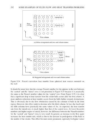
Figure 9.34 Forced convection heat transfer from spherical heat sources mounted on
the wall
It should be noted here that the average Nusselt number for the spheres in the row between
the ‘central’ and the ‘lateral’ rows is not presented in Figure 9.35 because it is practically
the same as the Nusselt number values for the ‘central’ row. From Figure 9.35, it is clear
that a significant drop in heat transfer from the solder balls occurs after the first column. A
more uniform reduction in heat transfer occurs from the balls further towards downstream.
This is obviously due to the flow obstruction caused by the columns of balls in the front
region. However, this effect tends to decrease after the third column. In fact, the fourth and
the fifth columns have practically the same values of Nu. As expected, the heat transfer
rate from the lateral rows is much higher than that of the central rows. At lower Reynolds
numbers and higher angles of attack, however, the difference between the Nusselt numbers
for the ‘central’ and ‘lateral’ rows is very small. In general, an increase in the flow angle
increases the heat transfer rate, which is due to the increase in participation of the balls at
the middle of the cluster. This effect becomes more prominent, especially for higher values