
Page 362 - Fundamentals of Water Treatment Unit Processes : Physical, Chemical, and Biological
P. 362
Flocculation 317
s ffiffiffiffiffiffiffiffiffiffiffiffiffiffiffiffiffi
0.25
P(slot)
(11:30)
G ¼
mV(slot)
0.20
where 1
k(slip factor) 0.10 V(slot) is the volume of water through which h L (slot) is
G is the velocity gradient for baffle slot (s )
0.15
3
dissipated (m )
11.5.4.2.1 End-Around Flocculation Basins
0.05 Figure 11.18a and b shows a top view and side view, respect-
2
k =0.074+ 0.007 rpm, R =.93
ively, for a hypothetical system. Dimensions are indicated as
proportions with respect to the channel width, B (see Haarh-
0.00
0 5 10 15 20 25 off, 1998, pp. 142–152). Following the method of Haarhoff,
rpm (rev/min) the outcome of a design should be the channel width, B
(the ‘‘master variable’’), the number of channels, n(channels),
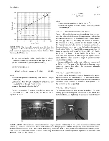
FIGURE 11.16 Slip factor plot generated from data from first the proportions, p, q, w, and r, and the headloss through the
compartment of flocculation basin of 76 L=min (20 gpm) pilot slot, h L (slot). Tables 11.10 and 11.11 summarize data from 12
plant located at Engineering Research Center, Colorado State plants, as compiled by Haarhoff (1998, pp. 143, 144). Facili-
University, Fort Collins, CO.
ties B and C in Table 11.9 and Facility P6 in Table 11.10
show data for a sequence of three stages for tapered floccu-
(for an over-and-under baffle, v(baffle) is the velocity lation. The two tables indicate a range of practice for the
between bottom edge of the baffle and floor of basin) sample of 12 facilities.
2
g is the acceleration of gravity (9.806650 m =s) Design guidelines for end-around baffles are summarized
in Table 11.11. The goal of the design is to have an even,
The power dissipated is continuous energy loss along the successive channels
(Haarhoff, 1998, p. 144).
P(slot) ¼ Q(slot) rwater g h L (slot) (11:29)
11.5.4.2.2 Tapered Flocculation
where The basin may be designed for tapered flocculation by adjust-
P(slot) is the power dissipated by flow around a single ing the slot width, i.e., increasing the slot width in the down-
baffle (W) stream direction such that the velocity is reduced sufficient to
Q(slot) is the flow through baffled basin (and around any result in a lower headloss, as calculated by Equation 11.28
3
single baffle or through ‘‘slot’’)(m =s) that conforms to the G specified.
3
rwater is the density of water (kg=m )
11.5.4.2.3 Flow Variation
The velocity gradient, G, is the same as defined previously, The downstream control may be used to maintain the same
i.e., Equation 10.5, but with P(slot) as defined as in velocity gradients throughout all channels in the basin. For
Equation 10.43, i.e., decreased flows, the depth may be decreased proportionately
(a) (b)
FIGURE CD11.17 Flocculation and sedimentation finished designs (animated walk through of Fort Collins Water Treatment Plant, 2000
Addition. (a) Animation 1 Flocculation Basin—Plate Settlers Walk-Through upstairs—PAK1B AVI (excerpt shows flocculation basins).
(b) Animation II Flocculation Basin—Plate Settlers Walk through downstairs—PAK1A AVI (excerpt shows corridor between basins; paddle-
wheel motors are visible on the walls). (Courtesy of Kevin Gertig, Water Resources & Treatment Operations Supervisor, FCWTFP and Kevin
Heffernan, CH2M Hill, Inc., Denver, CO.)