
Page 364 - Fundamentals of Water Treatment Unit Processes : Physical, Chemical, and Biological
P. 364
Flocculation 319
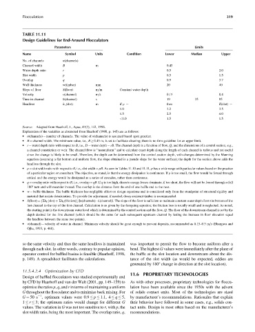
TABLE 11.11
Design Guidelines for End-Around Flocculators
Parameters Limits
Name Symbol Units Condition Lower Median Upper
No. of channels n(channels)
Channel width B m 0.45
Water depth ratio r 0.5 2.0
Slot width p 0.5 1.5
Overlap q 0.9 3.7
Wall thickness w(timber) mm 20 40
Slope of floor S(floor) m=m Constant water depth
Velocity v(channel) m=s 0.15 0.4
Time in channel u(channel) s 19 35 95
Headloss h L (slot) m if p ¼ then K(slot) ¼
1.0 3.2 3.5
1.5 2.5 4.0
<1.0 1.5 1.5
Source: Adapted from Haarhoff, J., Aqua, 47(3), 142, 1998.
Explanation of the variables as abstracted from Haarhoff (1998, p. 145) are as follows:
. n(channels) ¼ number of channels. The value of n(channels) is assumed based upon practice.
. B ¼ channel width. The minimum value, i.e., B 0.45 m, is set to facilitate cleaning; there is no firm guideline for an upper limit.
. r ¼ water:depth ratio with respect to B, i.e., D ¼ water depth ¼ rB. The channel depth is a function of flow, Q, and the dimensions of a control section, e.g.,
a channel constriction or weir. The channel flow is ‘‘nonuniform’’ and to calculate exact depth along the length of each channel is tedious and not useful
since the change is likely to be small. Therefore, the depth can be determined from the control section depth, with changes determined by the Manning
equation (assuming a flat bottom and uniform flow, the slope obtained is a pseudo slope for the water surface); the depth for the section above adds the
headloss through the slot.
. p ¼ slot width ratio with respect to B, i.e., slot width ¼ pB. As seen in Tables 11.10 and 11.11, p has a wide range with particular values based on the practice
of a particular region or consultant. The objective, as stated, is that the energy dissipation is continuous. If p is too small, the flow would be forced through
critical and the energy would be dissipated as a series of cascades, rather than continuous.
. q ¼ overlap ratio with respect to B, i.e., overlap ¼ qB.If q is too high, discrete energy losses dominate; if too short, the flow will not be forced through a full
1808 turn and will meander instead. The overlap is the distance from the end of one baffle end to the next.
. w ¼ baffle thickness. The baffle thickness has negligible effect on design equations and is considered only from the standpoint of structural rigidity and
material that resists deterioration. To provide for adjustment, if needed, decay-resistant timber is recommended.
. S(floor) ¼ {Sh L (slot) þ Sh L (friction)}=[n(channels) L(channel)]. The slope of the floor is sufficient to maintain constant water depth from the bottom of the
last channel to the top of the first channel. Calculation is as given by the foregoing equation; the friction loss is usually small and is neglected. As noted,
the starting point is the downstream water level which is determined by the control section and the flow, Q. The floor of the downstream channel is set by the
depth desired for the first channel (which should be the same for each subsequent upstream channel by letting the increase in floor elevation equal
the headloss between the same two points).
. v(channel) ¼ velocity of water in channel. Minimum velocity should be great enough to prevent deposits, recommended as 0.15–0.3 m=s (Bhargava and
Ojha, 1993, p. 468).
so the same velocity and thus the same headloss is maintained was important to permit the flow to become uniform after a
through each slot. In other words, contrary to popular opinion, bend. The highest G values were immediately after the plane of
operator control for baffled basins is feasible (Haarhoff, 1998, the baffle at the slot location and downstream about the dis-
p. 149). A spreadsheet facilitates the calculations. tance of the slot width (as would be expected, eddies are
generated by 1808 change in direction at the slot location).
11.5.4.2.4 Optimization by CFD
11.6 PROPRIETARY TECHNOLOGIES
Design of baffled flocculators was studied experimentally and
by CFD by Haarhoff and van der Walt (2001, pp. 149–159) to As with other processes, proprietary technologies for floccu-
optimize the ratios p, q, and r in terms of maintaining a uniform lation have been available since the 1930s with the advent
G throughout the flocculator and to minimize back mixing. For of solids contact units. Most of the technologies are sized
1
G ¼ 50 s , optimum values were 0.9 p 1.1, 4 q 5, by manufacturer’s recommendations. Rationales that explain
1 r 3; the optimum ratios would change for different G their behavior have followed in some cases, e.g., solids con-
values. The variation in G was not too sensitive to r, with p, the tact units. Design is most often based on the manufacturer’s
slot width ratio, being the most important. The overlap ratio, q, recommendations.