
Page 365 - Fundamentals of Water Treatment Unit Processes : Physical, Chemical, and Biological
P. 365
320 Fundamentals of Water Treatment Unit Processes: Physical, Chemical, and Biological
11.6.1 TURBINE FLOCCULATORS 1930s. They are widely used, especially in small plant situ-
3
ations e.g., 0.876 m =s (20 mgd) plant capacity. They are
The use of axial flow and turbine impellers of the Rushton
viewed with disfavor by some (Burns and Roe, 1971, pp. 4–6)
type (Sections 10.3.3.4, 10.4.2.5, and Glossary of Chapter 10)
because of lack of control of each of the unit processes. An
for flocculation was investigated by Walker (1968), then
additional disadvantage is that the flow of water is likely to be
president, Walker Process Equipment, who used a 1676 mm
distributed nonuniformly below the sludge blanket. The flow of
(66 in.) Rushton impeller in a 12.2 m (40 ft) diameter by 4.6 m water willseek its own path of least resistance through the sludge
(15 ft) tank with 1.52 m (5 ft) depth of submergence. The
blanket, thus creating a channel of higher velocity flow leaving
circulation patterns for the axial flow impeller was up and
much of the sludge blanket an inert mass. The advantage in
around with return flow to the impeller eye. While Walker
their use is that three unit processes, i.e., rapid mix, floccula-
was striving for uniform turbulence, the tests showed that the
tion, sedimentation, are combined in one unit with consequent
large eddies that predominated in the reactor volume were not
smaller size than the three unit processes as separate units.
efficient in flocculation, i.e., consistent with later theory.
11.6.2.1 Principles
11.6.2 SOLIDS CONTACT UNITS The processes in a solids contact unit start in the rapid mix
where the coagulant chemicals and the raw water are mixed and
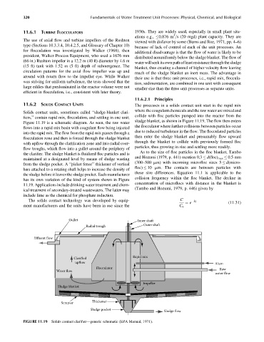
Solids contact units, sometimes called ‘‘sludge-blanket clari-
collide with floc particles pumped into the reactor from the
fiers,’’ contain rapid mix, flocculation, and settling in one unit;
sludge blanket, as shown in Figure 11.19. The flow then enters
Figure 11.19 is a schematic diagram. As seen, the raw water
the flocculator where further collisions between particles occur
flows into a rapid mix basin with coagulant flow being injected
due to reduced turbulence in the flow. The flocculated particles
into the rapid mix. The flow from the rapid mix passes through a
then enter the sludge blanket and presumably flow upward
flocculation zone and then is forced through the sludge blanket
through the blanket to collide with previously formed floc
with upflow through the clarification zone and into radial over-
particles, thus growing in size and settling more readily.
flow troughs, which flow into a gullet around the periphery of
As to the size of floc particles in the floc blanket, Tambo
the clarifier. The sludge blanket is fluidized floc particles and is
and Hozumi (1979, p. 441) mention 0.3 d(floc) max 0.5 mm
maintained at a designated level by means of sludge wasting
(300–500 mm) with incoming microfloc sizes 5 d(micro-
from the sludge pocket. A ‘‘picket fence’’ thickener of vertical
floc) 10 mm. The contacts are between particles with
bars attached to a rotating shaft helps to increase the density of
these size differences. Equation 11.1 is applicable to the
the sludge before it leaves the sludge pocket. Each manufacturer
collision frequency within the floc blanket. The decline in
has its own variation of the kind of system shown in Figure
concentration of microflocs with distance in the blanket is
11.19. Applications include drinking water treatment and chem-
(Tambo and Hozumi, 1979, p. 446) given by
ical treatment of secondary-treated wastewaters. The latter may
include lime as the chemical for phosphate reduction.
The solids contact technology was developed by equip- C kz
¼ e (11:31)
ment manufacturers and the units have been in use since the C o
Gullet Inner shaft
Radial trough Outer shaft
Effluent flow
Clarified Rapid mix
upflow Alum
Flocculator Raw
Water flow
water flow
Impeller
Sludge blanket
Scrapter Thickener
Sludge pocket
Sludge flow
FIGURE 11.19 Solids contact clarifier—generic schematic (EPA Manual, 1971).