Page 368 - Fundamentals of Water Treatment Unit Processes : Physical, Chemical, and Biological
P. 368

Flocculation                                                                                     323


            11.12 Characteristics of Full-Scale Paddle Wheel by      same as Basin #1, except that there are only two blades
                 Mathematical Model                                  per arm. Radial distances to the center of each blade
                 Given                                               are: r 1 ¼ 241 mm, r 2 ¼ 368 mm.
                 A flocculation basin is to be designed for Q ¼ 0.263  Required
                   3
                 m =s (6.0 mgd) at T ¼ 208C.                         Determine the power versus rpm curve and the G
                                                                     versus rpm curve using a spreadsheet and show the
                 Required
                                                                     results on an associated plot.
                 (a) Calculate the power, P, required by the paddle
                                                        1
                     wheel using Table 11.6 such that G ¼ 60 s .
                 (b) Generate plots as in Figure 11.15a through d.  ACKNOWLEDGMENTS
                 Reference                                     Kevin Heffernan, PE, principal project manger, CH2M HILL,
                 Table 11.6, i.e., file ‘‘11.6FlocBDes.082105.xls,’’ is  INC., Denver office, provided the three-dimensional animated
                 copied and renamed, as file ‘‘TableCDprob11.12=  drawing files, seen as Figures CD11.17a and b. The anima-
                 11.6FlocBDes.082105.xls.’’                    tions were included by permission from both the City of Fort
            11.13 Algorithm for End-Around Flocculation Basin  Collins and CH2M HILL, INC. Heffernan was design
                 Given                                         manager and resident engineer during the construction of the
                                     3
                 Assume flow, Q ¼ 1.0 m =s.                     new flocculation basins and building, i.e., as illustrated in
                 Required                                      Figure CD11.17, during the period 1998–2000.
                 Set up a spreadsheet algorithm to design an end-around  Kevin Gertig, water resources and treatment operations
                 flocculator basin. Use headings to identify variables  manager, City of Fort Collins, was superintendent of the
                 with rows for the assumed numerical values with cal-  Fort Collins Water Treatment Facility during the aforemen-
                 culated values across. Show a design sketch, i.e., both  tioned flocculation capacity expansion. As with other projects,
                 plan and profile as well as the design spreadsheet.  Gertig was intimately involved with the flocculation system
            11.14 Plot of Power and G versus rpm for Paddle-Wheel  expansion and passed-on his knowledge freely as related to its
                 Flocculator                                   design, construction, and operation, which helped in formu-
                                                               lating this chapter.
                 Given
                 Data of Table CD11.7 give measurements for the pilot
                 scale flocculation basin of Figure 11.14. For this prob-  APPENDIX 11.A: DERIVATION OF CAMP
                 lem, consider the third basin, Basin #3, which is the  AND STEIN G FOR THREE-DIMENSIONAL CUBE
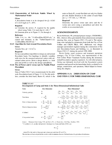

                         TABLE 11.A.1
                         Development of Camp and Stein G for Three-Dimensional Infinitesimal Cube
                         Term                  One Dimension               Three Dimensions a

                                              dv                 qu  qv   qu  qw    qv  qw
                         Velocity gradient
                                              dn                 qy  þ  qx  þ  qz  þ  qx  þ  qz  þ  qy

                                                  dv                  qu  qv   qu  qw    qv  qw
                         Total shear          t ¼ m             t ¼ m   þ   þ    þ    þ    þ
                                                  dn                  qy  qx   qz  qx    qz  qy
                                                                      "                           #
                                                                               2        2         2
                                                dv   dv dv       dv     qu  qv   qu  qw    qv  qw
                         Work of shear=unit time  ¼ m           t  ¼ m
                                              t

                                                dn   dn dn       dn     qy  þ  qx  þ  qz  þ  qx  þ  qz  þ  qy
                                                                    "                           #
                                                     2                       2         2        2
                                              P    dv                 qu  qv    qu  qw   qv  qw
                         Work of shear=unit time  ¼ m           F ¼ m
                                              V    dn                 qy  þ  qx  þ  qz  þ  qx  þ  qz  þ  qy
                                                                   "                           # 1=2
                                                                            2         2        2
                                                 dv                  qu  qv   qu  qw    qv  qw
                         G defined             G                 G      þ    þ   þ     þ   þ
                                                 dn                  qy  qx    qz  qx   qz  qy
                                                          1=2         1=2
                                                 dv   P             F
                         G in practical terms
                                              G
                                                 dn  ¼  mV      G ¼  m
                         Source: Abstracted from Camp, T.R. and Stein, P.C., J. Boston Soc. Civil Eng., October, 1943.
                         a
                           In addition to G, another defined term introduced by Camp and Stein (1943) was
                                                               P
                                                                                             (11:A:1)
                                                               V
                                                            F
                                                                      3
                           where F is the work of shear per unit volume per unit time (N m=m =s).
                         The term has not been adopted in this work in order to minimize the use of defined terms; it is given here for reference.
   363   364   365   366   367   368   369   370   371   372   373