
Page 486 - Fundamentals of Water Treatment Unit Processes : Physical, Chemical, and Biological
P. 486
Cake Filtration 441
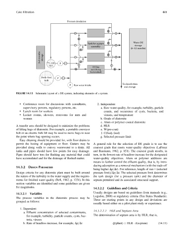
Precoat circulation
Waste DE
Tank for septum
assembly storage
(6–12 months)
3–6 months storage
Pre-coat
tank P
Off-line
tank (being
backwashed)
Body-feed P
tank
P Raw water intake To disinfection
and storage
FIGURE 14.13 Schematic layout of a DE system, indicating elements of a system.
. Conference room for discussions with consultants, 2. Independent
supervisory persons, regulatory persons, etc. a. Raw-water quality, for example, turbidity, particle
. Lunch room for workers counts, and occurrence of cysts, bacteria, and
. Locker rooms, showers, restrooms for men and viruses, and temperature
women b. Grade of diatomite
c. Alum or polymer-coated diatomite
A transfer area should be designed to minimize the problems d. HLR
of lifting bags of diatomite. For example, a portable conveyor e. W(pre-coat)
belt or an electric fork lift may be used to move bags to near f. C(body feed)
the point where bag opening occurs. g. Selected pressure limit
Easy cleaning should be provided for, with floor drains to
permit the hosing of equipment or floor. Gutters may be A general rule for the selection of DE grade is to use the
provided along walls to convey wastewater to a drain. All coarsest grade that meets water-quality objectives (LaFrenz
tanks and pipes should have low points for easy drainage. and Baumann, 1962, p. 851). The coarsest grade results, in
Pipes should have tees for flushing any material that could turn, in the lowest rate of headloss increase for the designated
have accumulated and for the drainage of flushed matter. water-quality objectives. Alum or polymer additions are
means to further control the effluent quality, that is, by intro-
ducing adsorption as a removal mechanism (with the trade-off
14.3.2 DESIGN PARAMETERS
being higher Dp=Dt). For reference, length of run ¼ (selected
Design criteria for any diatomite plant must be built around pressure limit)=Dp=Dt. The selected pressure limit determines
the nature of the turbidity in the water supply and the require- the tank design (for a pressure tank) and the diameter of
ments for finished water quality (Bell, 1962, p. 1254). In this septum permitted and its associated structural support.
section variables are identified and some guidelines are given
for magnitudes.
14.3.2.2 Guidelines and Criteria
14.3.2.1 Variables Usually designs are based on guidelines from manuals (e.g.,
Logsdon, 2008) or regulatory criteria (Ten States Standards).
The process variables in the diatomite process may be
These are starting points in any design and deviations are
grouped as follows:
usually based either on a pilot plant study or experience.
1. Dependent 14.3.2.2.1 HLR and Septum Area
a. Effluent concentration of selected contaminants,
for example, turbidity, particle counts, cysts, bac- The determination of septum area is by HLR, that is,
teria, viruses
b. Rate of headloss increase, for example, Dp=Dt Q(plant) ¼ HLR A(septum) (14:11)