
Page 485 - Fundamentals of Water Treatment Unit Processes : Physical, Chemical, and Biological
P. 485
440 Fundamentals of Water Treatment Unit Processes: Physical, Chemical, and Biological
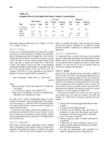
TABLE 14.4
Examples of Pre-Coat and Body-Feed Masses, Volumes, Concentrations
Pre-Coat Body Feed
Plant Capacity
Mass Volume C(slurry) PC Mass Volume C(slurry) BF
3
3
Plant (mL=day) (mgd) (kg) (L) (kg=m ) (kg) (L) (kg=m )
Las Virgines 56.78 15 136.4 946 144
Hearst Castle 9.09 378 24.0
Mills 75.70 20 159 1325 120
Saratoga 15.14 4 11.36 1,250 9.1
Rawlins 32.55 8.6 273 1136 240 136 11,355 12.0
The velocity range for a DE slurry is 1.0 v(pipe) 1.83 m=s point, for example, Microdact, with recording by computer
(3.5 v(pipe) 6ft=s). software (the signal is calibrated by an instrument reading
and the instrument is calibrated to a standard at a specified
14.3.1.2.3 Pumps frequency).
For pre-coat, a centrifugal pump may be used since a simple
circulation is all that is required; in addition, the water flow 14.3.1.2.5 Control System
from a centrifugal pump may be stopped by a valve without To control the flows, actuated valves have been available
building up excess pressure. The duration of the pre-coat step since the 1980s along with pumps controlled by micro-relays
is about 15 min. To use one volume change per min for the (Mirliss, 2002, p. 14). The actuated valves and the pumps may
slurry tank gives a pump size, Q(pre-coat) ¼ V(pre-coat)= be set to operate based on signal levels, that is, pressure, time,
(1 min). The headloss will be due only to the plumbing turbidity, etc., that may be set by the operator using the
configuration initially (which probably is negligible) but will software, for example, Wonderwaret.
rise to the pre-coat headloss at the end of the cycle, for
example, 10–20 kPa (2–4 psi), depending on the grade of 14.3.1.3 Layout
diaomite. The power required will be determined as Figure 14.13 is an illustrative layout showing a module of
four DE tanks. The point is that through proper pipe layout
P(pre-coat pump) ¼ Q(pre-coat) g h L (pre-coat) and the use of an adequate number of ball valves, about any
w
(14:10) configuration is possible. Whatever the configuration, its logic
should be self-evident. The system should have two mod-
where ules for redundancy with each module having 2 tanks. For
P(pre-coat pump) is the power required to circulate pre- small systems, however, a module may be one tank, with a
coat (watts) minimum of two modules. The backwash system is not shown
3
g w is the specific weight of water (9808 N=m ) in Figure 14.13, but is depicted in Figure 14.2c.
h L (pre-coat) is the headloss of pre-coat circulation flow The floor area needed is the sum of the areas used by
when pre-coat is deposited (m water) each module (e.g., two tanks per module, four tanks per
module, etc.). Other kinds of functions requiring floor area
For body feed, a positive displacement pump is recom- include
mended, for example, a positive displacement rotary progres-
sive cavity pump (e.g., a Moynot) will avoid pressure pulses. . A dock area for receiving bagged diatomite and other
The motor should be direct current in order to provide for materials
variable body-feed flow. . A storage area for bagged diatomite
For the raw-water pump, a rotary screw (progressive cav- . A transfer area for breaking bags and transfer of
ity) pump may be used if the flows are not too high, since the diatomite to a slurry tank (the transfer area should
flow is constant for a given motor rotation velocity. A direct be designed to alleviate any problems of DE dust)
current motor permits the raw-water flow to be adjusted from . A bin, for storage of spent DE
one run to the next. . Outside storage for weeks or months accumulation
of spent DE
14.3.1.2.4 Instruments . A laboratory for bench instruments and any wet
Flow meters, pressure gages, temperature sensors, turbidity chemical analyses deemed advisable and for calibra-
meters, and perhaps on-line particle counters are required for tions of on-line instruments
operation. Each instrument category is available as an analog . An office for administrative tasks (computer for
sensor (i.e., 4–20 mA) that can be attached to an interface reports to regulatory agency, storing data, etc.)