
Page 483 - Fundamentals of Water Treatment Unit Processes : Physical, Chemical, and Biological
P. 483
438 Fundamentals of Water Treatment Unit Processes: Physical, Chemical, and Biological
assemblies, for example, wet-cake discharge, vertical oriented atmosphere and the pump is on the effluent side of the filters,
tank-vertical septum leaves, vertical tank-horizontal leaves, as creating a negative pressure within the septum.
well as different kinds of septum materials and construction.
14.3.1.1.3 Septum
The sizes of single tanks may be in the range of 914 d(tank)
1829 mm (36–72 in.) with 6 N(leaves) 34 (Durco Filters
The most common septum shape is the vertical leaf. As seen
by Ascension Industries, 2009). A system may be purchased
in Figure 14.11, the vertical leaf filter is a disk with septum on
as a ‘‘package’’ from a manufacturer or the tank–septum
both sides with vertical orientation. To permit the buildup of
system is purchased with components designed and obtained
cake and to provide for the uniform circulation of diatomite
separately. For smaller systems, a skid-mounted ‘‘package’’
slurry, without cake erosion, the discs should be spaced suf-
system may be more practical and for larger systems, individ-
ficiently far apart.
ual design may be more appropriate.
The septa have been made of a variety of materials, for
example, stainless steel wire cloth, synthetic fabrics, and
14.3.1.1 Equipment porous stone. The stainless steel wire cloth fits most of the
As noted previously, a variety of septum shapes have been criteria for a suitable septum material. Required openings in
provided by manufacturers along with different kinds of tanks one direction are 0.13 mm (0.005 in.) (Bell, 1962, p. 1245).
and approaches to septum cleaning. A system design always A sieve size of U.S. Standard 60, however, has an opening of
involves 2 tanks, each with its own set of components. In 0.25 mm (a Tyler 60 sieve has the same opening), which was
other words, the system design is modular, that is, the same used at Vacaville. Generally, the septum openings are larger
design is repeated for each tank. This means also that there is than the coarsest grades of DE. Bridging over the openings
no theoretical limit to the size of an installation. occurs as the pre-coat is circulated; once the bridging starts,
the pre-coat is formed.
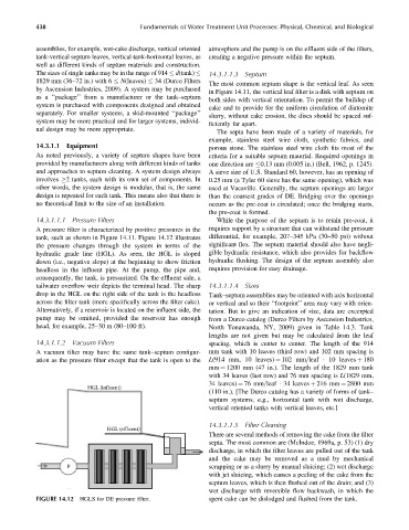
14.3.1.1.1 Pressure Filters While the purpose of the septum is to retain pre-coat, it
A pressure filter is characterized by positive pressures in the requires support by a structure that can withstand the pressure
tank, such as shown in Figure 14.11. Figure 14.12 illustrates differential, for example, 207–345 kPa (30–50 psi) without
the pressure changes through the system in terms of the significant flex. The septum material should also have negli-
hydraulic grade line (HGL). As seen, the HGL is sloped gible hydraulic resistance, which also provides for backflow
down (i.e., negative slope) at the beginning to show friction hydraulic flushing. The design of the septum assembly also
headloss in the influent pipe. At the pump, the pipe and, requires provision for easy drainage.
consequently, the tank, is pressurized. On the effluent side, a
tailwater overflow weir depicts the terminal head. The sharp 14.3.1.1.4 Sizes
drop in the HGL on the right side of the tank is the headloss Tank–septum assemblies may be oriented with axis horizontal
across the filter tank (more specifically across the filter cake). or vertical and so their ‘‘footprint’’ area may vary with orien-
Alternatively, if a reservoir is located on the influent side, the tation. But to give an indication of size, data are excerpted
pump may be omitted, provided the reservoir has enough from a Durco catalog (Durco Filters by Ascension Industries,
head, for example, 25–30 m (80–100 ft). North Tonawanda, NY, 2009) given in Table 14.3. Tank
lengths are not given but may be calculated from the leaf
14.3.1.1.2 Vacuum Filters spacing, which is center to center. The length of the 914
A vacuum filter may have the same tank–septum configur- mm tank with 10 leaves (third row) and 102 mm spacing is
ation as the pressure filter except that the tank is open to the L(914 mm, 10 leaves) ¼ 102 mm=leaf 10 leaves þ 180
mm ¼ 1200 mm (47 in.). The length of the 1829 mm tank
with 34 leaves (last row) and 76 mm spacing is L(1829 mm,
34 leaves) ¼ 76 mm=leaf 34 leaves þ 216 mm ¼ 2800 mm
HGL (influent)
(110 in.). [The Durco catalog has a variety of forms of tank–
septum systems, e.g., horizontal tank with wet discharge,
vertical oriented tanks with vertical leaves, etc.]
14.3.1.1.5 Filter Cleaning
HGL (effluent)
There are several methods of removing the cake from the filter
septa. The most common are (McIndoe, 1969a, p. 53) (1) dry
discharge, in which the filter leaves are pulled out of the tank
and the cake may be removed as a mud by mechanical
P scrapping or as a slurry by manual sluicing; (2) wet discharge
with jet sluicing, which causes a peeling of the cake from the
septum leaves, which is then flushed out of the drain; and (3)
wet discharge with reversible flow backwash, in which the
FIGURE 14.12 HGLS for DE pressure filter. spent cake can be dislodged and flushed from the tank.